Multiple Plumages
This tutorial outlines the recommended steps for setting up and simulating multiple instances of Carbon Plumage within one simulation.
The Plumage Introduction tutorial explains how to use a basic Carbon Plumage and it is strongly recommended to study that tutorial first before continuing with this tutorial.
Although a Carbon Plumage allows to create thousands of unique feathers based on individual scale values and type interpolation between three base feathers, there are scenarios where a single Carbon Plumage is not sufficient.
Amongst them are scenarios where:
- more than 3 base feathers are wanted/needed.
- feathers are made from different geometry (e.g. highly tessellated vs low-poly feathers).
- some feathers are soft (cloth and rigid shaft) and some are hard (rigid body).
- the feather behavior varies so much that it is easier to split feathers into different plumages.
Most of the geometry and simulation setup when dealing with multiple Carbon Plumage nodes in a single simulation is straight forward and can be learned in the Plumage Introduction tutorial.
However, there are certain aspects which need further attention.
Dealing With Plumage Overlaps
In this tutorial, we use three individual plumages, and a total of seven base feathers. Plumage 1 overlaps with Plumage 2, and Plumage 2 additionally overlaps with Plumage 3.
Below is shown the graph up to the Carbon Distance Scatter nodes.
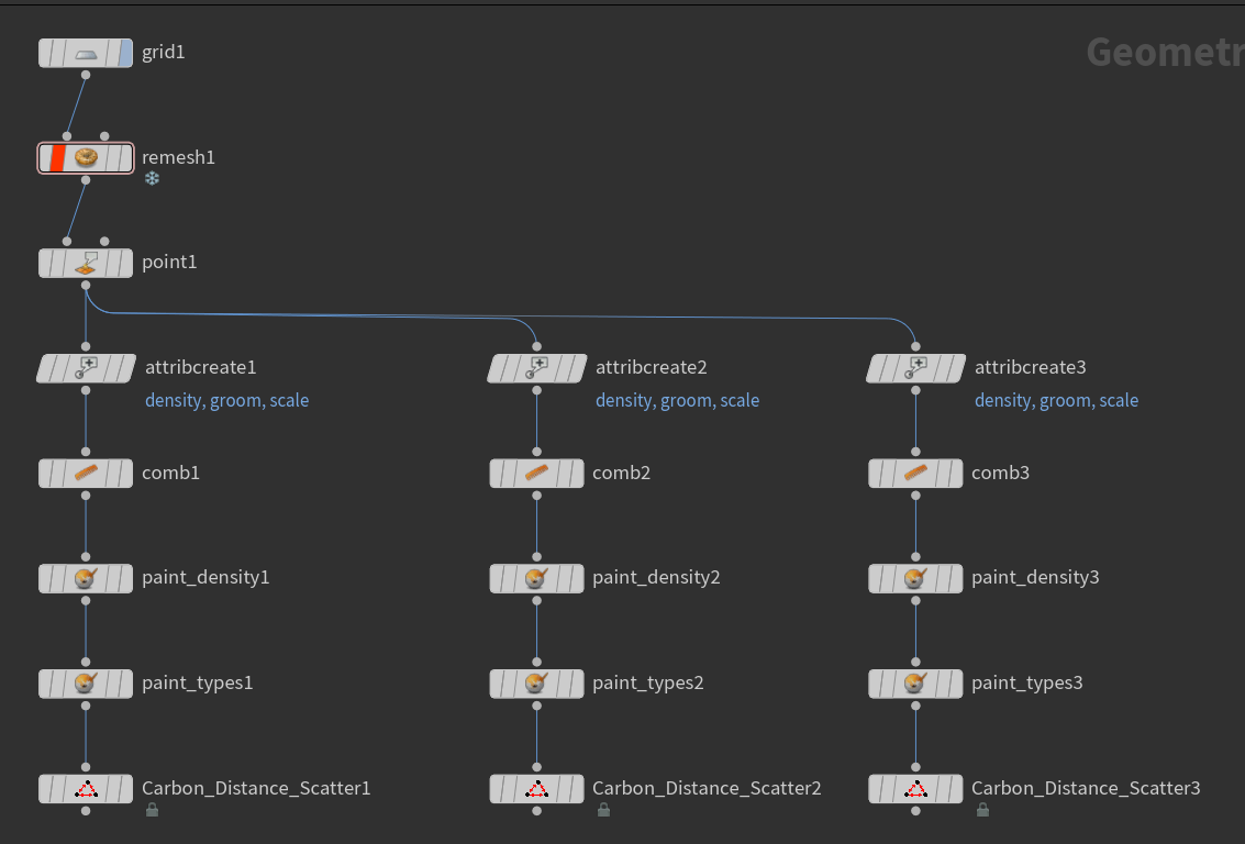
Graph up to Distance Scatter nodes for three individual plumages.
The scale is uniformly set for each plumage in attribcreate1, attribcreate2 and attribcreate3. All other attributes (groom, density and type) are painted.
Note
A neat trick for only spawning feathers on certain areas of a surface is to set the density to 0 where no feathers should be created.
The screenshot below shows the results after scattering points.

Distance Scatter results for three individual plumages (Grid overlaid).
The big problem that arises when using overlapping plumages is that some points (feather roots) will be too close to each other, which can already cause corruptions in the start pose for the simulation. The following two screenshots show the initial state and then a cleaned up state where a minimum distance between any two points is guaranteed again.

Before and after cleaning up points which are too close to each other. (Grid overlaid)
In order to fix an overlap area, the corresponding point geometries have to be merged together. To ensure that they can be split again later, create a point attribute (attribcreate_plumage1 and attribcreate_plumage2), e.g. plumage and set the value for the first geometry to 1 and for the second geometry to 2.
Next, merge them and attach two Fuse nodes. In the first Fuse (fuse1), Snap all points with a Snap Distance which is equal to the minimum value of Distance for Numerion_Carbon_Distance_Scatter1 and Numerion_Carbon_Distance_Scatter2. In fuse2, Consolidate all of these points by setting Distance to a value smaller that Snap Distance. Do not forget to toggle Keep Unused Points, as otherwise the geometry will be cleaned completely.

Fuse nodes.
After this step, all points in the overlap area that have been newly created/merged have invalid color values and possibly invalid plumage values, e.g. 1.5.
Adding an Attribute Wrangle allows to recalculate the correct color values and set a valid plumage value. There are three important VEX functions:
- rand(seed): Returns a random value between 0.0 and 1.0. Requires a seed.
- xyzdist(geometry, point, primitive number, barycentric coordinates): Returns the distance of point to the closest position P on the geometry. This finds positions on the surfaces of the geometry, not just point positions. Stores the primitive number of the primitive containing P and the position of P as barycentric coordinates.
- primuv(geometry, attribute, primitive, barycentric coordinates): Returns the value of attribute on geometry at the point located on primitive at barycentric coordinates.
Attribute Wrangle fixes the plumage value if it is neither 1 nor 2. Based on the interpolated value and the rand functions, the value is set to either 1 or 2.
Additionally, the type of each point is recalculated to match the paint maps created in paint_types1 and paint_types2. Same is done for scale and groom.
And at last, split the geometry back into plumage 1 and 2 by deleting all points with the opposite plumage value (happens in delete1 and delete2). Also, remove the plumage point attribute with attribdelete1 and attribdelete2.
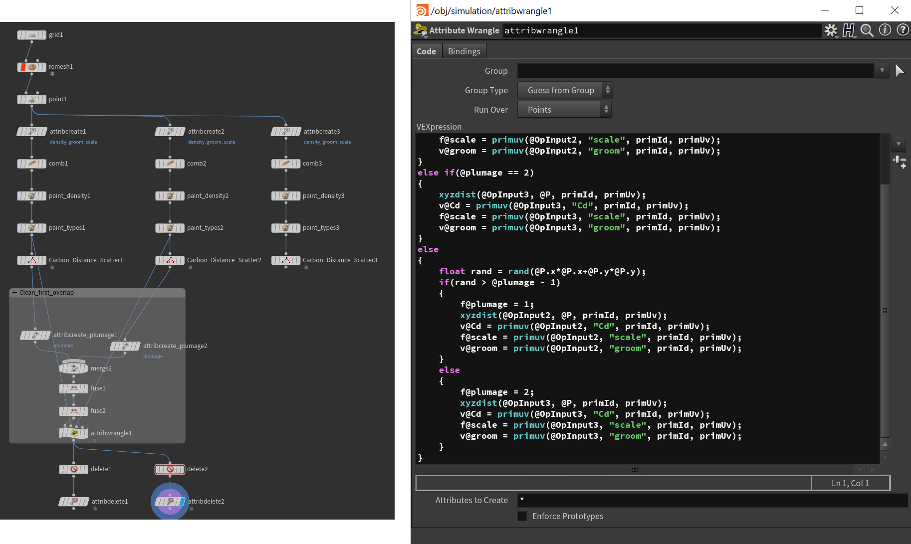
Nodes required for the clean-up process.
After this, repeat the process for each overlap, i.e. the overlap between Plumage 2 and Plumage 3 in this case, then attach Carbon Plumage Geometry nodes.
Using nodes like Bend allows to quickly animate the surface geometry.
Furthermore, let’s add a Carbon Flow that affects in towards the end.
The final simulation graph is shown below.

Final simulation graph for the three plumages.
Colliding Feathers
Having neighboring plumages or overlapping plumages will most likely lead to inter-plumage feather collision. This especially occurs when animating the feather angles/aperture to move all feathers from their starting orientation to their final orientation. Ensure that the Swing Stiffness and Twist Stiffness are set low enough to allow the feathers to push each other without causing geometry corruptions.
Final Simulation

Final simulation of the three plumages.