Garment Processor
Garments are often designed in dedicated packages such as Marvelous Designer or Optitex. These packages can export “thin” simulation meshes and thicker render meshes, (that encase the sim mesh). For many applications these render meshes are good enough for final use. Also, it’s helpful even for Hero movie characters to quickly preview something with the thicker render meshes rather than thin sim meshes. We have put together a Carbon Garment Processor workflow (macro) to support the import of simulation and render meshes and it includes a highly optimized deformer to map render meshes to sim mesh with very little processing overhead.
For this tutorial, we use the Carbon Garment Processor to import and setup a simple T-Shirt.
The T-Shirt is made up from panels, and has:
- Thin simulation geometry panels (typically lower resolution than render geometry)
- Thick higher resolution render geometry panels
- A number of higher res render geometry details (i.e. stitches, button holes etc.)
Details can also include buttons or these can be set up and simulated separately as rigids.
The number and names of panels of simulation geometry and render geometry must match. The names of the detail geometry are irrelevant.
See separate tutorials on exporting simulation and render geometry from garment design packages.
Step 1 - Import Geometry
As a first step, we import all required geometry, i.e. Simulation Panels, Render Panels, and Details geometry. In this tutorial, my geometries come from fbx files.
Note
Unfortunately, some of these fbx contain unused/disconnected points, so we had to add Clean SOP nodes. If you start from clean geometry, there should not be a need for a Clean node, but it is always best to double check at this stage to prevent issues from occurring later in the process.

Imported geometry.
Step 2 - Verify Geometry
Simulation Panels and Render Panels must be unpacked geometry and contain a
primitive attribute called name.
name is used to create individual Cloths for the Simulation, as well as for
matching reference and deformer geometry.
Carbon Garment Processor will not work without this attribute!
Next, please verify that both the Simulation Panels and Render Panels have a
name primitive attribute.
You can do this but middle-mouse-button clicking on the network nodes.
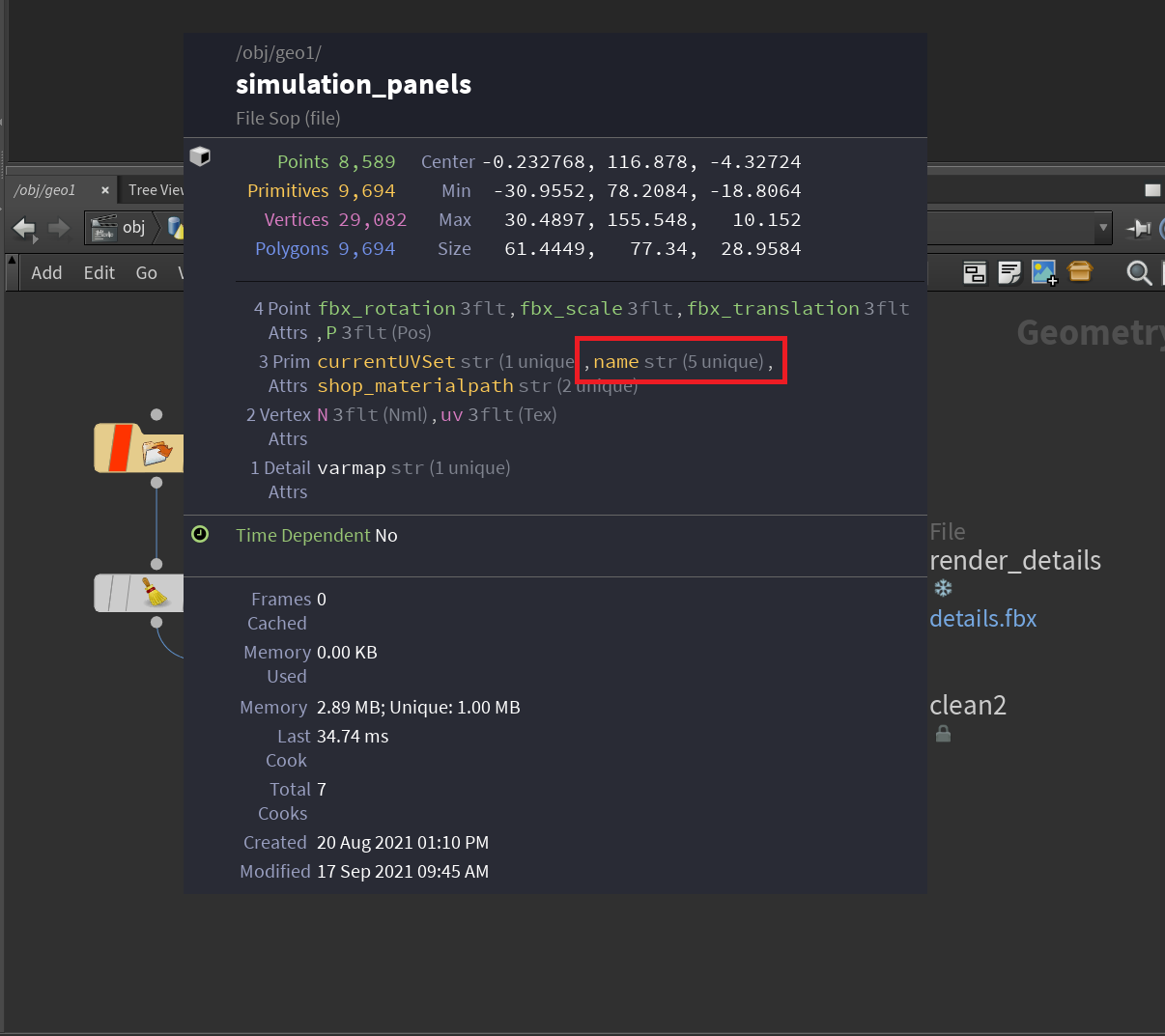
name primitive attribute.
The information panel also let’s us verify that there are 5 unique names, i.e. we will end up with 5 Carbon Cloth nodes.
Note
If you import your geometries from OBJ, they will most likely not have
a name attribute, but have primitive groups instead.
You can automatically create the name attribute from these groups by
attaching a Name from Groups node, and changing the Group Mask parameter
from piece* to *.
Verify Simulation Panels
Before we verify that Simulation Panels and Render Panels are compatible, we
recommend double-checking that all Simulation Panels are described correctly
by the name attribute.
For that, create a Carbon Garment Processor node and attach clean1 to both Input #1, and Input #2 of the Carbon Garment Processor.

Verify Simulation Panels.
Based on the name attribute, the Carbon Garment Processor
separates the geometry into panels, which each will later become
Carbon Cloth nodes.
Warning
At this stage, if any two (or more) panels have the same color, this means that they would be combined into a single Carbon Cloth during the process. This needs to be manually fixed, but goes beyond the scope of this tutorial.
Verify Render Panels
Now, plug the output of clean3, i.e. the Render Panels, into Input #2 of the Carbon Garment Processor.
The Carbon Garment Processor automatically runs a compatibility test, and matches Render Panels to Simulation Panels. If there is no warning or error on the Carbon Garment Processor node, this was successful. If there is a warning or error on the node, it will tell you which panels are incompatible so that you can fix the issue.
There are no issues with the geometry in this tutorial, but please see below for an example output where there are incompatible panels:
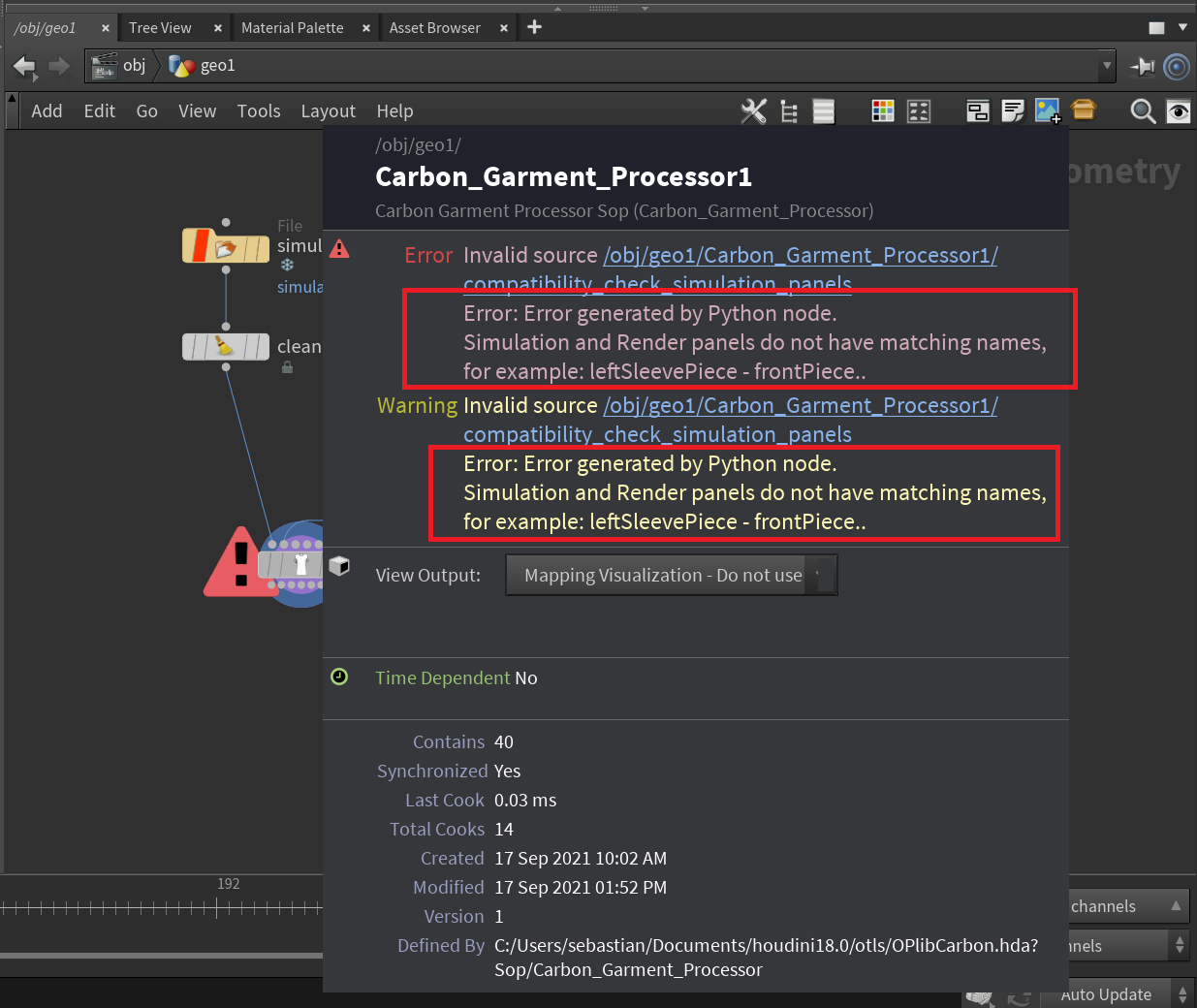
Verify Render Panels example output for incompatible geometry.
The error above states that there is either no frontPiece panel in the Render Panel, or no leftSleevePiece in the Simulation Panel.
Step 3 - Creating the Simulation Network
Now, add a Carbon Simulation and Carbon Cloth Material node to the network and set the corresponding parameters on the Carbon Garment Processor:

Adding Carbon Simulation and Carbon Cloth Material nodes.
Next, press the Create Simulation Subnet button. This will automatically create new subnet containing the full simulation setup. Step out of the subnet and connect its output to the Carbon Simulation node. Now place the blue Display flag on the simulation node and you can see the Carbon Simulation Physics Draw of the complete setup.

Simulation Setup
There are 4 major components on the Carbon Garment Processor that allow you to control/modify the simulation:
Reset Simulation button: Click this to reset the Carbon Simulation after you made any changes.
Cloth Material: All Carbon Cloth are connected to this Carbon Cloth Material. You can easily swap for a different Carbon Cloth Material, or edit the existing one to change the Carbon Cloth behavior.
Physics Draw: These dropdowns are connected to all internal nodes of each type. This is very useful for debugging, as you might for example want to hide all Carbon Cloth nodes to be able to verify that the Carbon Stitching nodes are set up correctly.
Stitching: For ease of use, all internal Carbon Stitching can be controlled via this section. Please refer to the Carbon Stitching reference page for more information.
Note
One very important parameter that needs to be set for this tutorial is Self Stitching. When Self Stitching is unticked, it will disable all stitchings where Cloth A is the same as Cloth B. This can prevent unwanted stitchings from being created, but the T-Shirt in this tutorial relies on self-stitching as the sleeves on are wrapped around the arms, and the collar also stitches to itself in the back.
Note
You may need to tweak the Stitching settings either now or later to have the correct Carbon Stitching parameters. After tweaking the settings, you need to reset the simulation to see the impact of the change. Please refer to Carbon Stitching for more information on the individual parameters.
At this stage you can either tune and extend the simulation setup, or continue on to Step 4 for adding Detail Mapping. Step 4 and 5 do not impact the simulation, so you can work on each aspect independently at your own time.
Step 4 - Creating the Detail Mapping
Now, we want to deform our Render Panels and Details geometry according to the simulation output. But before we can move to Step 5 - Creating Mesh Deformers, we need to map each Detail geometry to a Render Panel.
For this, go back to the Carbon Garment Processor node, i.e. select it and place the blue Display flag on it.
Now, connect the output from clean2 to the Render Details input (Input #3) on the Carbon Garment Processor node.
Then switch to the Detail Mapping tab.
You can now see the details geometries in addition to the render panels. But while the render panels are colored individually, the details are not. They are grey, as they have not been mapped yet.

Unmapped Details
Press the Create Mapping button to automatically create mappings based on a proximity search algorithm. Each detail geometry will now be colored in the color of the render panel that it has been matched to.
Additionally, list of all mappings appear in the UI.

Mapped Details
If you want to change the colors, you can do this by setting a different Random Color Seed
If you want to edit the mapping, for example if the mapping algorithm did not map a Detail to the desired Render Panel, there are two options:
- To change the mapping of an individual Detail via selection in the viewport, use the Change Individual Mapping button. First, press the button, then select a Detail mesh in the viewport. Next, hold Shift on your keyboard and select the new Render Panel mesh that the Detail should be mapped to. Finally, press Enter on your keyboard.
- Edit mappings by changing the Render Panel dropdowns in the Mappings list.
Note
You can now change the mappings at any stage, even after completing Step 5 - Creating Mesh Deformers. But note that you need to press the Update All Mappings button in the Mesh Deformers tab for any changes to be applied.
Step 5 - Creating Mesh Deformers
Now that the simulation is set up (Step 3), and the Detail mapping is complete (Step 4), we can create the Carbon Mesh Deformer setup.
On the Carbon Garment Processor, switch to the Mesh Deformers tab, and press Create Deformer Subnet. This will create a subnet that contains the complete Carbon Mesh Deformer graph setup.
If you step out of the subnet, you can see that it is connected to the Carbon Garment Processor node:

Mesh Deformer Setup
All other parameters in the Mesh Deformers tab are connected to their respective Carbon Mesh Deformer parameters of the Carbon Mesh Deformer nodes in the Deformer Setup subnet.
For example, if you want to export all Carbon Mesh Deformer mapping data to files, simply point to a folder, and press Export.
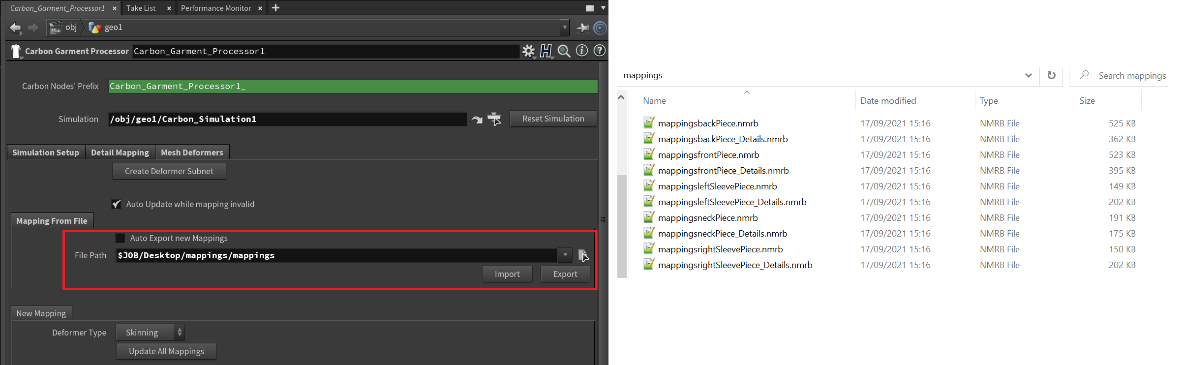
Mesh Deformer Mapping export.
Please refer to the Carbon Mesh Deformer reference page for more information.