Tissue Setup
This tutorial outlines the recommended workflow for setting up and using tetrahedrons in the Carbon Tissue node. Additionally, it incorporates advanced techniques such as applying painted attributes. It is recommended to first study the Avatar Cloth, the Tetrahedralization and the Painted Attribute Maps in that order, as they cover all necessary know-how needed to easily comprehend this tutorial. Furthermore, please refer to the Carbon Tissue reference for details about all tissue specific parameters.
The remainder of this tutorial teaches how to create a mattress object from tetrahedrons, place it on a ramp-shaped Carbon Collider, set non-uniform attributes on the mattress, and then drop a spherical Rigid Body (Carbon Rigid Body Macro) on it to show the different behaviors induced by the painted attributes.
Creating The Mattress Geometry
First, create a box that matches the desired mattress shape. We don’t want perfectly sharp edges, so let’s add a Poly Bevel node. Next, in preparation for a Remesh, add all current edges to a edges group.

Creating a group for all hard edges.
Then, apply a Remesh node and set the Hard Edges Group. This is important to preserve the overall shape as well as possible.

Remeshing the box while maintaining all hard edges.
Finally, tetrahedralize the geometry with the Tetrahedralize node.
Warning
The Tetrahedralize node is not available anymore in Houdini versions 18.5 and up. Please use Tet Conform instead.

Final tetrahedal geometry.
Make sure that the One Surface Face per Tetrahedron checkbox is ticked. Simulating tetrahedral geometry is the most stable when each individual tetrahedron only has one surface face.
Also, make sure Avoid Boundary Modifications is ticked as well.
After this, we need to decide how we want to structure the mattress on the inside: Uniform tetrahedralization, or non uniform tetrahedralization. Since the geometry is not very thick, it’s best to apply a uniform tetrahedralization. For this, let’s set the Max Size parameter to something similar to the Remesh’s Target Size parameter.
Warning
In Houdini versions 18.5 and up, instead of Tetrahedralize, please please use Tet Conform instead. Also, Max Size is then called Max Tet Scale.
The Remesh’s Target Size parameter is set to 0.012, so if we set Max Size to 0.012 as well, we end up with pretty much perfectly uniform tetrahedrons. The big downside of this is that the overall number of tetrahedrons generated is very large. Roughly 212k, which is a large number and will slow down the simulation quite a bit without really adding to the quality of the simulation. So, let’s set the Max Size parameter to 0.018, which gives us roughly a maximum volume ratio of 3.3 between tetrahedrons with largest volume compared to tetrahedrons with smallest volume. And the total number of tetrahedrons in the mattress geometry is reduced to about 72k.
See also
Please refer to Tetrahedralization for more information.
Painted Attributes On The Mattress
In order to achieve different behaviors within the same geometry, we need to add/paint point attributes onto the geometry, which are read by Carbon.
See also
Please refer to Painted Attribute Maps for more information on painted attributes.
The following parameters influence the squashing behavior of the Carbon Tissue node for this tutorial:
The most efficient way is to only create one of the attributes in a Carbon Attribute Copy node, Attribute Create node, Point Wrangle node, etc. For example Stretch Stiffness. Then, paint that attribute, or set it via a script, and then add a Carbon Attribute Copy node to copy the values to all other attributes.
Using A Script For The Gradient
The mattress is to be painted with a gradient, where a larger part should be all red, while only a small area on the left hand side should remain white. Painting an exact gradient by hand using the Paint node can be tedious. In many situations, it is much easier to use a script to set attribute values.
Let’s add a Point Wrangle node, which creates the Stretch Stiffness point attribute gradient. We are taking advantage of the fact that the mattress geometry ranges from exactly 0 to 1 in x direction, and base stretchStiffness on the value of x. After creating the attribute, it’s best to visualize it using a Color node.

Using a script for the attribute gradient.
Now, append a Carbon Attribute Copy node and copy the values from stretchStiffness to all other attributes mentioned above.

Copying stretchStiffness to all other necessary attributes.
Arranging The Mattress and Adding Props
Next, place the mattress geometry ramp and a sphere geometry. This concludes the geometry setup.

Geometry Setup.
Setting Up The Simulation
The Simulation is made from 3 object nodes (5 Carbon nodes):
- Mattress, which is a Carbon Tissue.
- Sphere, which is a Carbon Rigid Body Macro (contains Carbon Rigid. Carbon Shape, Carbon Body).
- Ramp, which is a Carbon Collider.
Additionally, there is the Carbon Simulation node.
The Ramp and Sphere parameters are shown below.
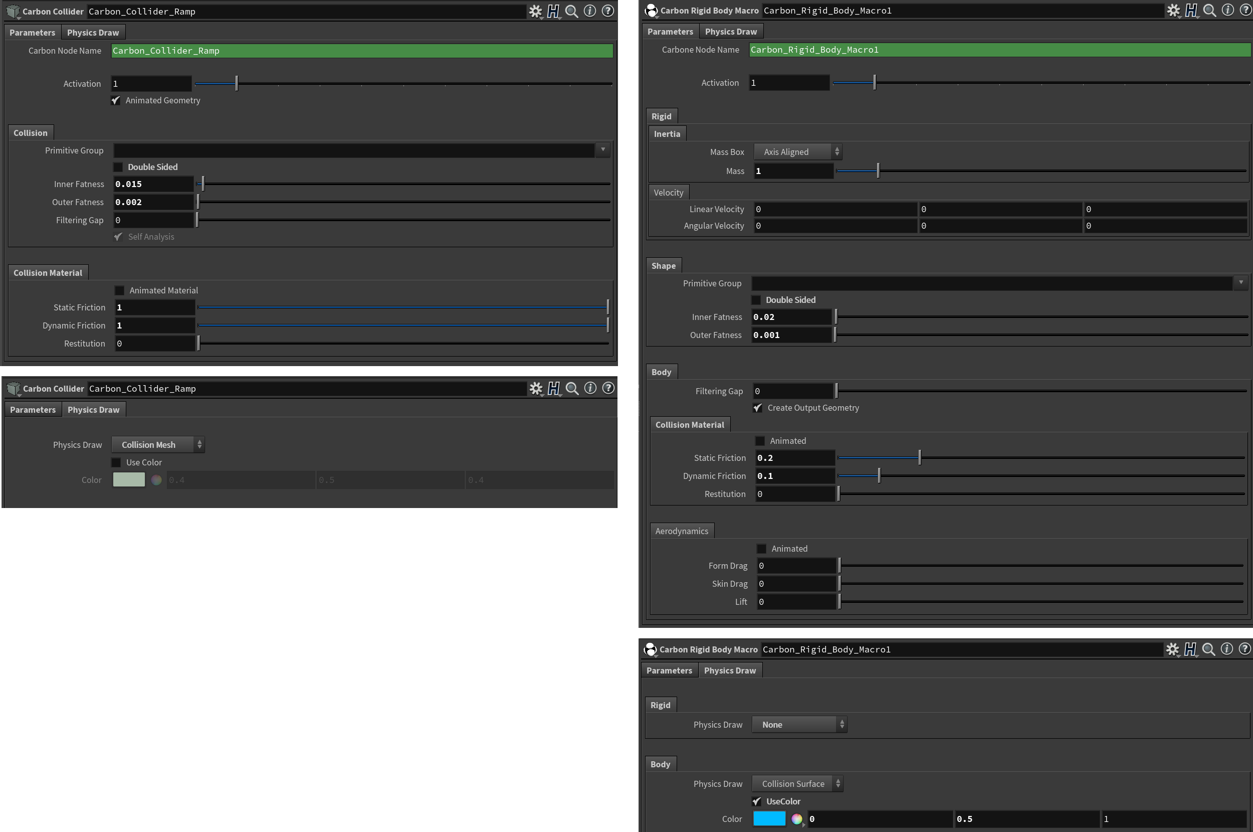
Ramp and Sphere parameters.
The simulation is set up with almost all default values. Let’s just increase Iterations and Subdivisions to 20. 10 Iteration and 10 Subdivisions are generally only recommended for very simple setups with a small number of primitives.
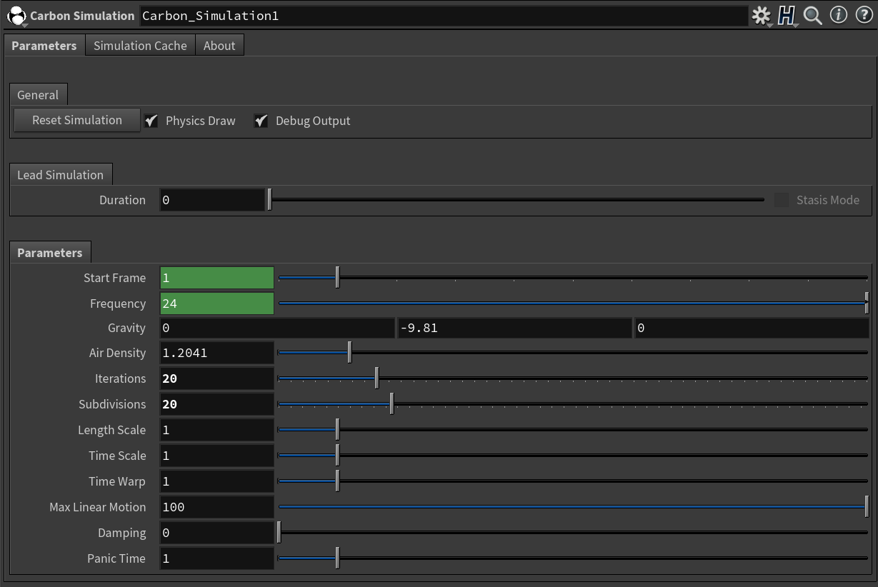
Simulation parameters.
See also
For more information on setting up Simulation and Collider parameters, please refer to Avatar Cloth.
Setting Up The Carbon Tissue Node
The mattress has been painted so that the top is unaffected and the bottom part is affected by the paint map. The target is to turn the mattress very stiff and non-deformable at the top and have it very soft and deformable at the bottom. The screenshots below show how to set up the main parameters for the Carbon Tissue node. Please refer to the hip file at the bottom of this page for all other parameters.
Collision

Collision parameters.
For scenarios like this, Self-Collide can be toggled off as there is no twisting or folding of the mattress.
Note
Disabling the self-collision check increases the simulation speed and should be disabled whenever possible.
Single Sided Collision
When using single sided geometry, the usage of an Outer Fatness is not required but it increases stability, collision detection accuracy and also reduces penetration singularities. Moreover, it may be used to create a virtual cage/buffer which can later be filled with a high-resolution model for rendering. If a small outer fatness is wanted, keep in mind that values lower than about two magnitudes smaller than the edge lengths of the mesh do not produce any visible difference.
Inner Fatness is the most complicated parameter of the Carbon Tissue node. It describes the penetration depth limit at which it becomes impossible to tell which face provides the correct separation direction for collision detection and resolution. Therefore, the value is very much dependent on the tissue simulation. If a Carbon Tissue node is subject to heavy deformations, a large Inner Fatness could mean that objects get pulled through another part of the collision surface as they enter the large Inner Fatness cone of a face, i.e. the simulation will literally blow up. On the other hand, using a larger Inner Fatness increases determinism of the collision detection and overall stability.
The following guidelines help find a suitable Inner Fatness value:
- Always use an Inner Fatness less than half of the width of the smallest part of the geometry, e.g. for a box, half of the smallest edge length.
- Small deformations: A generous Inner Fatness, as mentioned in the previous point, can be applied.
- Large deformations: The Inner Fatness should be smaller than the size of the smallest tetrahedron.
- Heavy deformations: The Inner Fatness should be set to 0, while relying on double sided collision with a generous outer fatness to prevent objects from going through one another.
Double Sided Collision
In case of this tutorial, the mattress undergoes very large deformations at the bottom and even a small Inner Fatness will lead to the mattress getting pulled through itself.
We therefore enable Double Sided Collision Collision and set a small Thickness value.
More information on how to set up fatness values can be found in Fatness / Thickness.
Painted Attributes
What we are trying to achieve in this scenario is to control the softness of the mattress. Up top, it should be quite firm and towards the bottom very soft. Since we painted the attributes to be 1 at the bottom end, we are to apply negative Range values, meaning we tune the base parameters to achieve the look for the upper part of the mattress and then set the range values to soften up the bottom part.
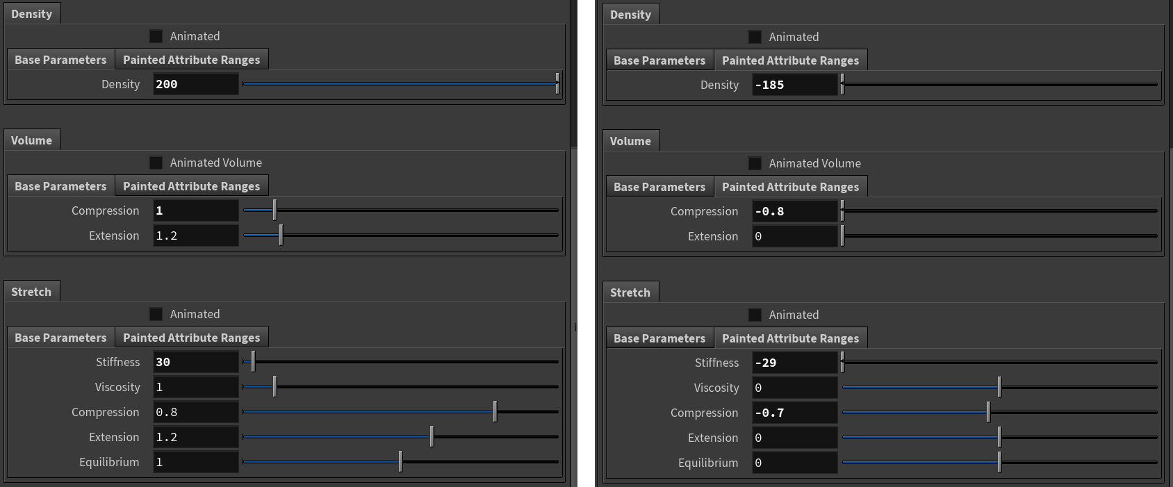
Setting the painted attributes parameters (Base values on the left and Range on the right).
As for the Surface constraints of the epidermis, let’s lock down Compression and Extension to get some nice creasing on the side of the mattress as the ball pushes its way towards the bottom.
For more information about extension and compression, please refer to Compression/Extension.
Final simulation.