Plumage Introduction
This tutorial outlines the recommended steps to create and simulate a Carbon Plumage.
Carbon Plumage is an array of one or more feathers where each feather is a hybrid object, containing Carbon Rigid elements and possibly Carbon Cloth parts. Each feather can be either fully rigid (a Carbon Rigid + Carbon Shape + Carbon Body), or made of a rigid shaft (Carbon Rigid) that is welded to a soft body (Carbon Cloth). Soft feathers nicely conform to the underlying surface geometry (Carbon Collider) and usually deliver more realistic results, while hard feathers simulate much faster. A Plumage takes 3 different feathers as input. A type attribute is used to interpolate between them and a scale attribute additionally scales the interpolated feathers independently, which can result in a single Plumage containing tens of thousands of unique feathers.
Working with Carbon Plumage is a 3 step process. First, create up to 3 feathers which are used for the Plumage and form the base of all feathers. Next, create the (animated) plumage structure that is required for the Carbon Plumage node by using the Carbon Distance Scatter and Carbon Plumage Geometry nodes. In the last step, the Carbon Plumage node is set up for simulation.
The remainder of this tutorial is split in three parts, explaining each step in detail.
Creating Feathers
A Carbon Plumage can consist of hard or soft feathers. Hard feathers are made from a Carbon Rigid + Carbon Shape + Carbon Body per feather, while soft feathers are made from a single Carbon Cloth per feather which is welded to a Carbon Rigid shaft.
In either case, all feathers are interpolated from 3 base feathers which need to have the same topology:
- Same number of points.
- Same triangles.
- Same vertices.
- Same edges.
This means that the points or triangles may not be reordered and the connection graph of the points has to be the same for all feathers.
Additional requirements:
- Feather’s Center of Mass must be at the origin (0,0,0).
- Feather must be oriented along Y-axis in XY plane (Y is up direction).
- The feather’s root / pivot, i.e. center-lowest point(s), must be on the y-axis.
- Feather’s front is facing towards the positive Z-axis, feather’s back is facing towards the negative Z-axis.
Note
Feathers may extend along Z-axis and may have a 3-dimensional bounding box. This could be either a closed 3-dimensional geometry, e.g. flat boxes as reptile scales for a hard plumage, or having thin feathers which are bent or twisted.
Hard Feathers
As hard feathers do not deform, there are no limits as to a minimum number of triangles recommended per feather.
Soft Feathers
The tessellation of the base feathers and placement/size of the rigid shaft strongly impacts their simulation behavior:
- While more triangles allow for more bending, simulation time might increase.
- A large rigid shaft adds stiffness and motion control but prevents feathers from conforming to a surface.
- If very deformable feathers are needed, restrain from using Delauney triangulated geometry as the randomness counteracts bending.
Below is shown an example of a good feather.
Good feather mesh.
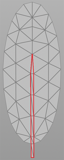
This feather has certain bending directions predisposed within the geometry by containing long (straight) lines and having only a short rigid shaft (highlighted above in red).
The screenshots below highlight such lines (red for horizontal bend and blue for vertical bend).

Bending predispositions.
Note
- Depending on the desired behavior, this feather might be too bendy already. There is no one-fits-all-needs feather.
- Certain behavior can only be achieved by a combination of tessellation and additional paintmaps for cloth parameters like bendStiffness.
- Try to avoid triangles that have two edges/points on the outline of the feather geometry. These flap too easily.
In this tutorial, we simulate a soft plumage whose 3 base feathers were derived from the feather geometry above:

3 unique base feathers.
Next, we need to define which points of the feathers are to be welded to the rigid shaft. For this, create a Point Group containing the attachment points on Feather 1.

Shaft point group.
Note
Always select more than a single line as this locks the twist axis. If one was to select points all located on a single line, the feathers would not be constrained for twisting and could rotate freely.
Warning
Always double-check that all feathers follow the rules outlined in the beginning of the Creating Feathers section. Especially pay attention to place the center of mass of each feather on the origin (0,0,0) and the bottom center of each feather on the y axis. Failure to comply with all requirements will likely result in unstable simulation results.
Creating Plumage Geometry
Every plumage starts from a simple surface on which feathers are to be spawned. Additionally, the surface can be animated. The screenshot below shows the initial stage of this collider geometry scene: An animated tube which stays still at first, then twists and then bends. These are common ranges of motion for animated characters on which a plumage is added.
Please refer to Houdini tutorials for information on how to create animated geometries.

Initial state of the collider geometry.
Next, close the tube, correct normals and turn it into a Carbon Collider for the simulation.

Creating the geometry for the Carbon Collider.
Please refer to the Avatar Cloth tutorial for in-depth information on how to set up a Carbon Simulation with a Carbon Collider.
There are three pieces of information that need to be stored in point attributes that are required for a Carbon Plumage: Information about the direction/orientation of all feathers, size of each feather, and type of each feather, which describes how it is composed from the 3 base feathers.
Grooming
Grooming is the process where the final direction/orientation of each feather is determined. As a result of this process, a vector of size 3 is stored as point attribute for each point of the surface geometry.
Houdini provides a Comb node which allows you to edit the normals of the surface geometry. To preserve the original normals (created in point_add_normal) override an attribute other than N. Create the attribute groom and initialize it with the normal vectors. Then toggle Override Normal on the Comb node and set the attribute to groom.

Setting up a Comb node.
It can be hard to see the results of the combing process. In order to get a temporary visualization, attach a Attribute Rename node and rename groom to N. Now, toggle Display Normals to visualize the result.

Temporary visualization of the edited normals.
Once the groom is satisfactory, remove the Attribute Rename node.
Scale
The scale is a single floating point attribute that additionally influences the size of each individual feather and is applied after the interpolation between the 3 base feathers.
The recommended process is to first create a point attribute to hold the scaling information, usually called scale, and initialize it with either 0 or the most common target scale. If almost all feathers are to receive a scale of 0.75, initializing scale to 0.75 saves time on the painting process.
Note
The values for scale must be greater than 0 but are not limited to a maximum value of 1.
After that, paint the desired scale values and smooth them to get fluent transitions between feathers.
For this tutorial, the idea is to have several large feathers on the right side and lots of small feathers towards the left.

Painting the feather scale.
Type
Painting the feather type, usually stored as color attribute Cd, creates each individual feather based on the 3 base feathers. Red stands for feather 1, green for feather 2 and blue for feather 3. Using barycentric interpolations, each feather is set to its interpolated shape, and receives the appropriate mass and fatness values for the Carbon simulation.
Painting for example a color of (0.5,0,0.5) returns a feather which is an exact median between base feathers 1 and 3.
For this tutorial, the large base feather 1 is located on the right (to go along with the scale paintmap), which then gradually turns into base feather 2 and finally transitions into the small base feather 3.

Painting the feather type.
Density
Before using the Carbon Distance Scatter node to create all feather roots, there is one optional feature. When using feathers of different size and scale, it is consequently necessary to control the number of feathers spawned per unit area. Where one could have 100 small feathers to cover an area, sometimes a few large feathers suffice.
Since the density is supposed to counter-balance the scale, the paintmap should be close to an inversion of the scale paintmap.
Note
A density value of 0 guarantees that no feathers are spawned. Unless this is intended, restrain from 0 values.

Painting the feather density.
Carbon Distance Scatter
The Carbon Distance Scatter node is a powerful node which combines Scatter and Fuse and additionally ensures that each generated point is placed on the surface of the input mesh.
First, set the Distance. This value indicates the minimum distance between any two generated points and has two advantages: It removes clusters to help generate a uniform distribution. Also, it ensures that no two feathers are spawned too close to each other, which would result in interpenetrating geometry.
There are two ways to exclude areas of a surface geometry from having feathers spawned on them. As mentioned before, when using a density attribute, sections with a painted value of 0 do not receive any feathers. Furthermore, the Group attribute provides a similar feature. If a primitive group is provided, only those primitives are considered for spawning feathers.
Next, adapt the Density Scale until satisfied with the number of generated points. Global Seed is a seed for the distribution function that calculates the randomized positions of each of the points.
Toggle Density Attribute and specify the attribute name if a density paintmap is available.

Using the Carbon Distance Scatter node.
Carbon Plumage Geometry
The Carbon Plumage Geometry node creates, updates and animates geometry that is suited for a Carbon Plumage.
The first input needs to be in the format created by the Carbon Distance Scatter in the last section, that is points with attributes containing information about grooming direction, feather scale and feather type.
The second input has to be the surface on which the points were created, in this case the initial non-animated tube.
The third input is optional and contains the animated surface for which the points of input 1 were created, in this case the tube animation.
Now, set the Groom Points Attribute Parameters names. These are the names of the point attributes describing groom vector, feather type and feather scale.
Next, untoggle Animated Groom as our groom is not animated and leaving it toggled off increases the simulation speed.
You should now see something like this:

Carbon Plumage Geometry.
Each of the triangles contains information for a single feather that will be spawned by the Carbon Plumage node.
The Carbon Plumage Geometry node also has a Guide Geometry option to give an indication of the plumage shape / feather layout.
Please note that the Guide Geometry itself does not have any influence on the resulting data or simulation. It simply allows a fast pre-visualization of the flattened and scaled feathers on without knowing the actual feathers. Length and Width scale the guide geometry triangles for better visualization.

Carbon Plumage Geometry Guide.
Setting Up A Plumage Simulation
Collider
As Carbon Plumage is always created on and from a surface, the surface is usually added to the simulation as a Carbon Collider.
In this tutorial, the collider is a tube of 1m length and 5cm radius. A Collider Outer Fatness of 0.001 (equals to 1mm), and a Collider Inner Fatness of 0.04 (equals to 4cm) are appropriate.
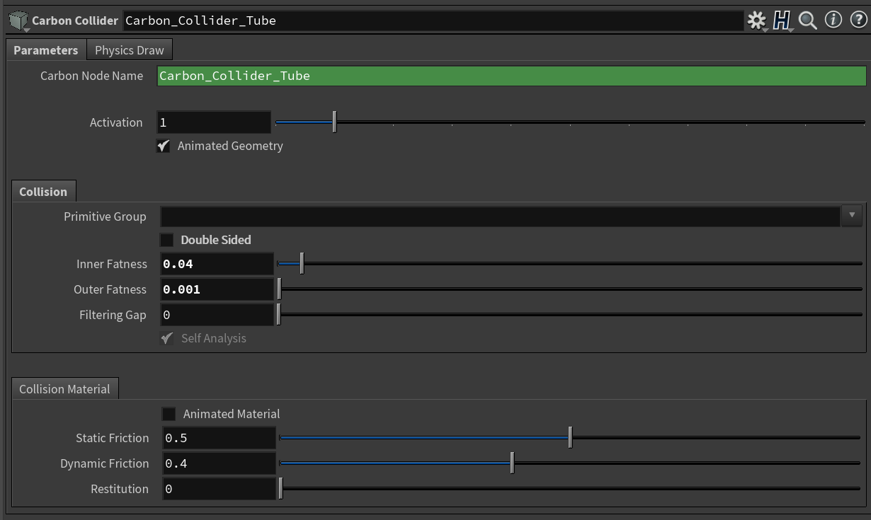
Parameters of the Carbon Collider node.
Plumage
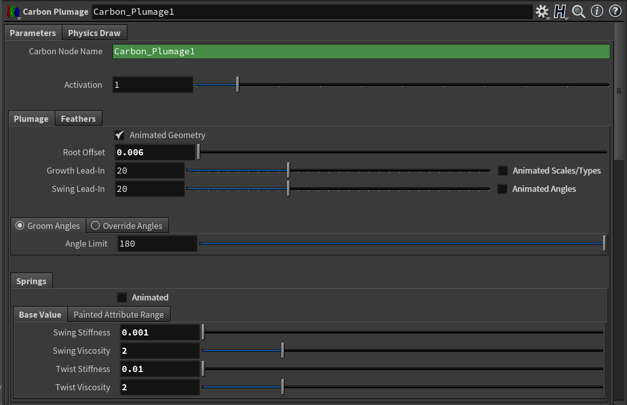
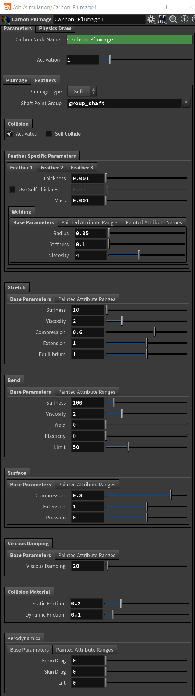
Plumage parameters of the Carbon Plumage node.
The plumage setup controls the plumage geometry and all global parameters like swing and twist, friction and aerodynamics.
- Animated Geometry
With the plumage/tube being animated, leave Animated Geometry toggled on.
- Root Offset
The Root Offset is a feather offset in surface normal direction. This is usually used to avoid collision issues with a Carbon Collider by setting this value to at least the Collider Outer Fatness if any collider is present.
In this tutorial, the Collider Outer Fatness is set to 0.001. This is the absolute minimum value required for the simulation. Often, when operating with small values, it is best to choose a slightly larger offset, especially since the collider is bending and the feathers also swing down. If the Root Offset is too small, you will get feathers that jitter / jump / pop. We chose 0.006 as Root Offset for this tutorial.
- Scale and Types
Animating scale to grow and shrink feathers is more than just a tool for special effects. Spawning feathers at a small size and growing them during lamination helps to ensure that no feathers are spawned inside each other. Setting a value v for Growth Lead-In that is larger than 0 starts the simulation with small feathers and automatically scale them over a period of v frames up to their intended size. Animating the scales or types heavily impacts the performance and scales animation is turned on internally only for the growth lead-in time and remains off afterward, unless manually overwritten by Animated Scales/Types.
- Angles
All feathers are initially spawned along the surface normal to minimize possible interpenetration. Similar to Growth Lead-In, Swing Lead-In provides an automated way of rotating the feathers to their final state. Setting a value v for Swing Lead-In that is larger than 0 starts the simulation with all feathers lined up along their surface normal and automatically rotate them over a period of v frames to their intended state.
Note
The Swing Lead-In is performed after Growth Lead-In.
If any angles are further animated, for example to create effects like spiking up feathers for a scared or angry bird, emulated interactive feather grooming, etc., toggle Animated Angles on, otherwise leave it toggled off to gain some performance.
There are two options to control the final angles. The first option utilizes the angles from the automatically generated angle primitive attribute on the Carbon Plumage Geometry. The Carbon Plumage Geometry node requires a groom vector to set the swing and twist axis of feathers. Based on the groom vector and the surface normal, the angle between groom and normal is extracted and stored. Choosing Groom Angles uses those angles. Setting Angle Limit to 180 applies the exact angles from the groom and the feathers are aligned with their respective groom vector. Values between 0 and 180 interpolate between normal and groom vector as target. Negative values invert the groom.
Second, Override Angles applies the same angle to all feathers in the plumage. This is the easiest way to set uniform angles, but due to the non-uniformity of most surfaces, this usually leads to some feathers conforming close to the surface and some still being partially lifted.
- Spring
Swing Stiffness and Swing Viscosity control the swing/flapping behavior of the feathers. High values for Swing Stiffness guarantee that the feathers stay close to the underlying surface while low values allow for a feeling of lightness and fluffiness.
Twist Stiffness and Twist Viscosity control the twist behavior of the feathers, which is the rotation around the shaft. Similar to the swing parameters, high values prevent additional feather movement.
There is no generally most suitable parameter setup for the spring parameters. Animated plumages with strong deformations require lower stiffness values to avoid corruption of the feathers while fast plumage animation relies on high stiffness values to ensure that the feathers follow the animation. It is recommended to start with low values for Swing Stiffness and Twist Stiffness and low values (1 or 2) for Swing Viscosity and Twist Viscosity, then to adjust these values as required. Starting with Swing Stiffness: To tune the values, set both stiffness values close to 0, turn off all Plumage and Collider animations, and run the simulation to see how the feathers behave during the growing and swinging process. If the value is too low, it will be very obvious, as you can see in the screenshots below. Increase the stiffness by a magnitude of 10 and try again; iterate until a value stiff enough is found. Then repeat this process for Twist Stiffness. Keep in mind that you might to adjust these values once you turn on animation again.
Too low Swing Stiffness (left) and too low Twist Stiffness (right).
Feathers
Feather parameters of the Carbon Plumage node.
A Carbon plumage takes up to 3 input feathers. See above in section Creating Feathers for information about how to best create suitable feathers. If only 2 different feathers are wanted for a plumage, ensure that feather 3 is not used by painting only red and green values for the feather type (See above at Creating Plumage Geometry).
Type
The type of plumage, either Hard Feathers, Soft Feathers
Hard feathers are fully rigid, i.e. each feather is composed of Carbon Rigid, Carbon Shape, and Carbon Body.
While they do not always conform to the underlying surface geometry and might not look as realistic as Soft Feathers, they simulate much faster (up to 60 times faster on modern desktops).
Hard feathers have two main applications:
- Provide fast pre-visualization results for feathers.
- Simulate hard shells, e.g. reptile scales, porcupine spines.
Soft Feathers contain a rigid shaft, defined by a point group on the first feather, and a soft shell which is welded to the shaft. The soft shell is equivalent to a Carbon Cloth object using the Face-Segment-Crease Cloth Model. All of their parameters are paintable but not animated.
In this tutorial, we use Soft feathers.
Shaft Point Group
Points to weld to the rigid shaft.
Note
For use with the Soft Feathers plumage type only.
Set this to group_shaft.
Collision
Activated:
Untick this box to remove all collision between this Plumage and itself and all other Carbon nodes in the same simulation.
If unticked, all other Collision parameters will be disabled, as well as all Collision Material and Aerodynamics parameters.
Note
A Plumage without collision activated cannot interact with any Carbon Flow nodes.
Self Collide
The parameter that has the biggest impact on the simulation speed among the cloth parameters is Self Collide. If toggled on, each feather is tested for self-collision. In general, this is not needed as only very large and bendy feathers have the potential to self-collide.
Feather Specific Parameters
Feather 1, 2, 3
- Thickness / Fatness
Please refer to the Avatar Cloth tutorial about setting up Thickness / Fatness.
Also, for more information about setting up Fatness values, refer to Fatness / Thickness.
Note
A Carbon Plumage can also handle 3-dimensional “feathers”, which could be porcupine spines or reptile scales. While Soft feathers use Thickness only, when using Hard feathers, for such geometry, it is recommended to work with a small Outer Fatness and rely on a larger Inner Fatness.
In this tutorial, all feathers receive an Thickness of 0.001, e.g. a thickness of 1mm per feather.
- Mass
The Mass refers to the total mass of the feathers in kilogram. This is an absolute value and should be set realistically. In this case, all feathers receive a mass of 0.001, which equals to 1 gram.
- Welding
Per default, all soft feathers are hard-welded to the plumage. This means, that their shaft is rigidly attached and can only swing and twist according to the Spring setup as shown above. For simple plumages, this is fully sufficient. On the other hand, more complicated plumages, where constraining situations are to be expected (between legs, armpits, etc.), it is recommended to work with a soft-welding by using a non zero Welding Radius. This allows for the shaft to move in over-constrained situations, reducing jiggling and increasing stability.
The recommended steps for achieving such a soft-welding are to first turn off any animation on the plumage and to also deactivate the underlying collider, if there is one. Now, set Welding Radius to a large value, e.g. 1. This removes the Lagrangian limit and allows to tune the Welding Stiffness to a value that is strong enough to hold all feathers in place under normal circumstances so that only feathers in over-constraining situations should deviate from the position where one would expect them to be in a zero radius/hard-welding setting. In the screenshot below, for example, it is obvious that the Welding Stiffness is too weak. It cannot even hold up the feathers under their own weight when gravity is applied.
Too weak of a Welding Stiffness
As it turns out, for this example, the default Welding Stiffness of 0.1 is a great value.
Next, activate the animation of the plumage and see if the stiffness is still strong enough and holds all feathers in place. In this case, it is.
The last step is to reactivate the collider and reduce the Welding Radius to a value big enough that it still prevents over-constraining situations and jiggling, but small enough to ensure that the complete plumage does not lose its overall shape and look. For this scenario, a radius of 5cm (0.05) is sufficient.
Note
All welding parameters are paintable. For examples of feathers using painted welding, please refer to the Examples & All Downloads section.
- Cloth Parameters
Soft feathers are each made from a Carbon Cloth object using the Face-Segment-Crease Cloth Model.
All of the cloth parameters are paintable but not animated.
For a step-by-step guide through the meaning of each parameter, please refer to Avatar Cloth. In general, start with high values for Stretch Stiffness (e.g. 100) and Bend Stiffness (e.g. 100) and Viscous Damping (20) and then lower the values until the desired behavior is achieved.
Final Simulation Setup
To complete the setup, add a Carbon Simulation node. It is useful to add some Damping to remove any potential small oscillations. Additionally, it is also recommended to use the Panic Time in order to avoid unnecessary simulation time in case the simulation blows up.

Final setup of the simulation
Note
If Growth Lead-In and Swing Lead-In are set to 0, all feathers are shown fully grown and at their final rotated state. This quick pre-visualization gives a general idea of how the grown and rotated feathers will look like.

Quick pre-visualization.
Make sure to set Growth Lead-In and Swing Lead-In back to their initial values after this.
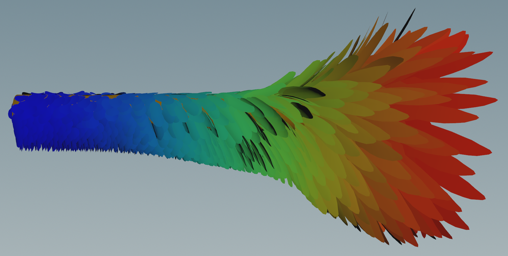
Final Simulation
Final simulation of the plumage.