Wrinkle
Carbon is very good at ironing out wrinkles in existing geometries, therefore removing unwanted creases which have been baked into the geometry. Using Carbon Cloth Flat Angle sets all existing angles, which larger than its value, to be flat. In Tailored mode, all reference angles are flat and the Flat Angle parameter allows to control the seaming angles’ limits.
But on the other hand, some creases are meant to be permanent. Typical cases for this include curtains, dress shirts with collars, skirts with pleats or pants with pleats.
The latter is used in this tutorial, which demonstrates how to set up and simulate permanent wrinkles, such as creases or pleats, for a Carbon Cloth node.
It is recommended to use the Tailored cloth mode for handling any types of garments that have been created using a virtual garment design tool. For introductory information on how to create a Tailored simulation with Carbon, please refer to Tailored Cloth Setup Tutorial before continuing with this tutorial.
Painting Wrinkles
As pleats are hard angle overwrites on user-defined creases, it is crucial to ensure that the pleat lines are a part of the geometry when creating a virtual garment in a design tool. Otherwise, the pleat will not form a straight line and will look undefined.

Start pose and reference panels of the pants.
The geometry setup for wrinkling comes from the painted attribute wrinkles. For introductory information about attribute painting and paint maps, please refer to the User Guide Painted Attribute Maps.
As geometry creases along edges, the reference angle between two faces that share an edge is determined by the average value of wrinklesDetail for the two points on that edge.
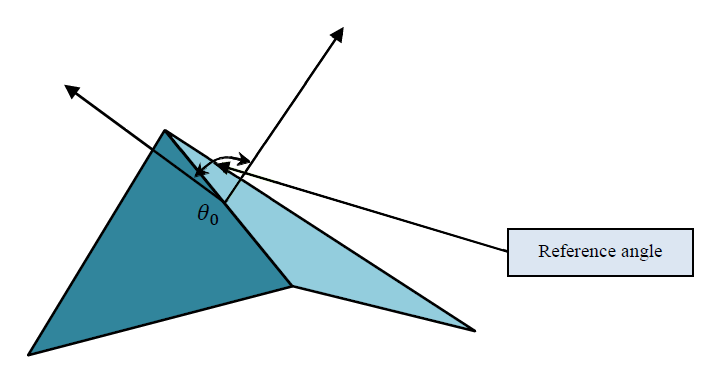
Wrinkles controls the reference angle between two faces.
A painted wrinkles value of 0.5 sets a reference angle of 0 degrees between the two faces. This corresponds to a flat geometry, i.e. both faces lie in the same plane.
Therefore set the initial value for the whole geometry to 0.5 and afterwards paint all areas where wrinkling is supposed to happen. Paint maps range from 0 to 1 and are used as multipliers.
The Wrinkles Limit parameter in Carbon Cloth controls the actual angular wrinkles limit of creases. A painted value of 0 then corresponds to -wrinklesLimit degrees and 1 corresponds to wrinklesLimit degrees. The final angular value for each segment then calculates as follows:
With \(avg_{paint}\) being the average of two wrinkle point attribute values across a segment, \(angle = wrinklesLimit *(avg_{paint}-0.5) * 2\).
While one could manually paint wrinkles, it is usually easier to create a point group containing all points that are along a “wrinkle line”, and use an Attribute Create SOP to initialize the wrinkles painted attribute from the group.

Selecting the point group.
Creating the wrinkles painted attribute from the group.

Creating the *wrinkles painted attribute from the group.*
Setting Wrinkles Limit
The final step is to set the Wrinkles Limit attribute value.
The Wrinkles Limit’s values range from -180 to 180 (degrees) and set the angular limit of the wrinkling, with negative values expressing an inversion of the wrinkles paint map. This can be useful if the initial paint map has been painted the wrong way around.
In this case, 90 is a suitable value to produce the expected creasing.
The simulation can now be run with the pleats clearly showing.

Final simulation result.