Goal Pose
This tutorial teaches an advanced art direction technique using goal posing.
Please refer to the Carbon Cloth reference, Painted Attribute Maps, and especially Goal Pose/Goal Skin.
The remainder of this tutorial is split into three parts. First, the base principles of goal posing are summarized. After that, two use cases demonstrate typical applications of goal posing. The first of these shows how to take a rigged, skinned and animated character and art direct the region of motion of a Carbon Cloth by goal posing parts of the cloth to the animation. The second example teaches how to use goal posing to perfectly loop a cloth simulation.
The Principles Of Goal Posing And How To Use It
Goal posing is a technique to create animation-driven physics simulation based on the use of a goal pose (the target) and a goal skin (the cloth).
In Carbon, goal posing is used by the Carbon Cloth and the Carbon Morph nodes.
Note
While the Carbon Morph only requires a single input, Carbon Cloth objects use a separate input for the goal (Input #3). The Enable Goal Pose toggle allows to turn the goal posing on and off without having to disconnect the Goal Pose input geometry. Refer to the Goal Pose/Goal Skin user guide for more in depth information about Goal posing.
The use of goal posing in a Carbon Morph differs from using it in Carbon Cloth objects. Morphs are intended to turn parts of an animated collider into cloth, which usually is targeted at solving animated collision geometry issues, like intersecting armpit or leg geometry, while goal posing a Carbon Cloth allows the creation of sophisticated effects such as seamless cloth simulation looping.
The following two scenarios demonstrate how goal posing is used on a Carbon Cloth node.
Rigging And Skinning
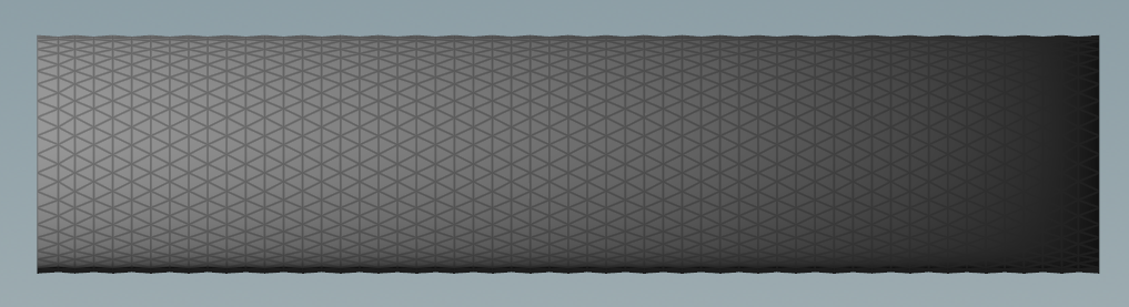
In this scenario, a kinematic chain of 20 bones, 10 on each side of an anchor point, sets the starting state. This structure can be seen below.

Kinematic chain made from 20 bones.
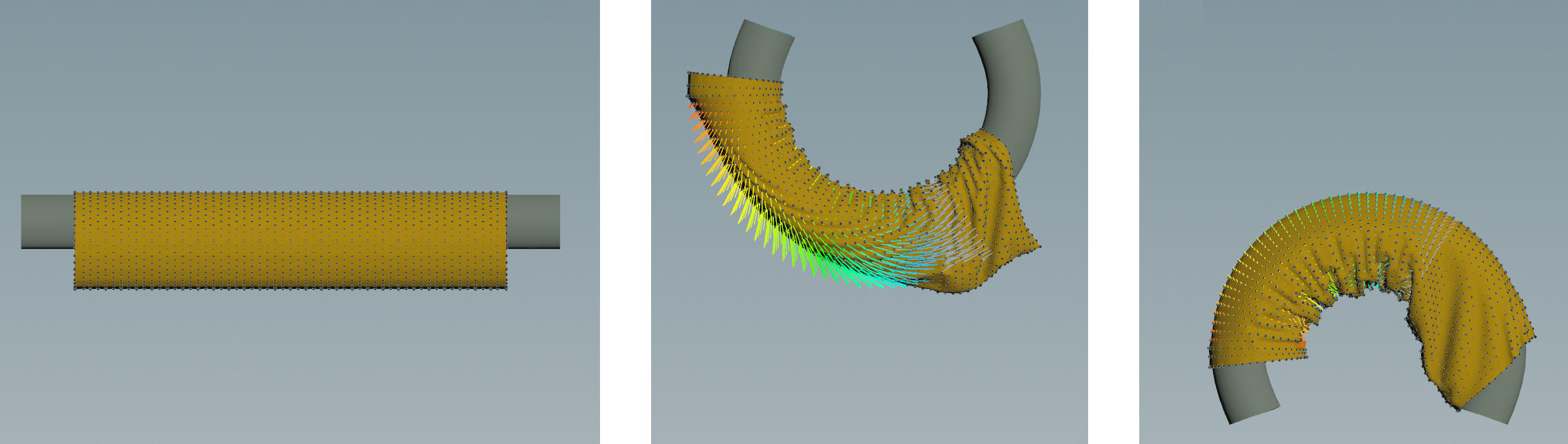
That chain is the rig for an arm-like geometry. Imagine an arm and a sleeve, both rigged and skinned with the bone structure above. The bones are then animated to bend upwards and downwards.

Starting pose and peak deformations of the skinned arm and sleeve.
Unfortunately, the sleeve geometry does not show many fabric-like features and rather looks like plastic.
By using this skinned animation as goal skin, its possible to goal pose all or parts of the sleeve with varying Goal Skin Strength values and create the desired art directed look.
Below is a simple paint map for the goalSkinStrength point attribute.
Paint map for the sleeve.
After that, apply the following values for the Carbon Cloth goal skin parameters:
- Base = 10
- Range = 50
- Lower Threshold = 0.25
- Upper Threshold = 0.77
All points of the sleeve geometry with a painted goalSkinStrength value lower than 0.25 are fully dynamic and are not constrained by the goal pose. On the other side, all points with values greater than 0.77 are fully kinematic and are equal to the goal pose at all times.
Goal posed sleeve.
Below is a comparison of the pure rigged and skinned animation (left) with the goal posed Carbon Cloth simulation.
Comparison of purely skinned geometry (left) versus a goal posed simulation (right).
Looping A Simulation
This scenario explains how to create a looping flag by goal posing.
A typical application for looping would be a fashion video of simulated cloth, of say 5 secs, that seamlessly loops. It is also possible to create a sophisticated interactive application with a decision tree of different transitions so that the cloth behavior can be changed in some way (maybe increased wind speed) and it seamlessly transitions to a new loop.
For the purpose of this tutorial, a flag is attached to a simple pole and is affected by a varying air flow. For more information on how to bind a Carbon Cloth to a Carbon Collider, please refer to Avatar Cloth. For more information on how to set up flows, please refer to Carbon Flow.
Now, create a basic flag geometry and add a paint map with a linear gradient, where all points located on the left edge receive a value of 1 and all points located on the right edge receive a value of 0. The painted attribute is goalSkinStrength.

Paint map for the flag.
Using a gradient is very important for looping a simulation, the reason for that will be explained below.
First, there is a common structure to any looping simulation scenario. It consists of three parts, split across two simulations:
- Simulation 1: Lead-in + Base simulation
- Simulation 2: Looping simulation
The Lead-in usually consists of 50 to 100 frames. Its main purpose is to get the simulation into a steady state. In this scenario, for example, the starting position is a flat flag, which will first drape downwards before it catches the air flow and starts waving in the wind.
The Base simulation then serves as the goal pose target for the Looping simulation. In the scenario, the chosen Lead-in is 50 frames, the Base simulation 100 frames, and the Looping simulation will be 150 frames, of which the first 50 are unconstrained, i.e. no goal posing active, and the final 100 frames are goal posed against the Base simulation. This way, the first frame of the Looping simulation is equal to the last frame, hence creating a loop.
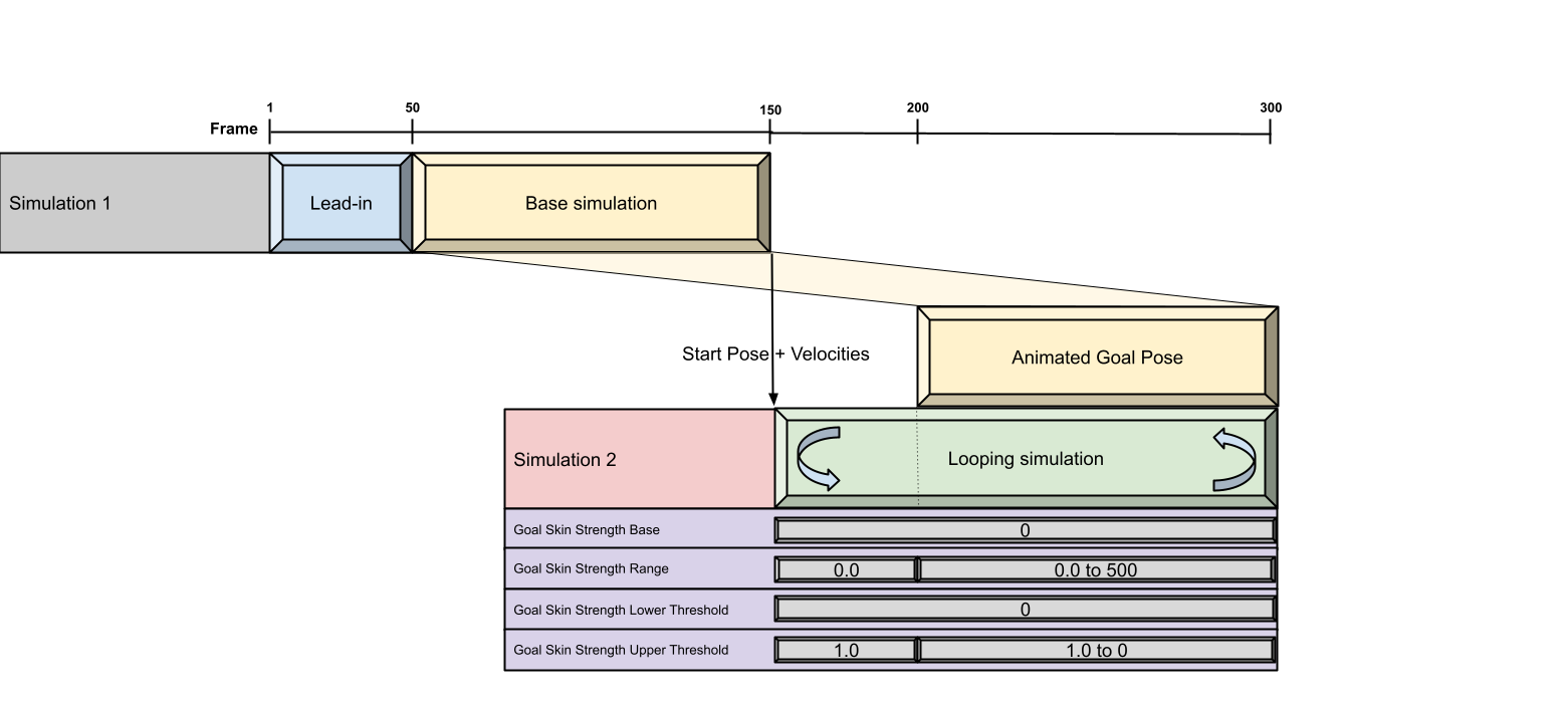
Schematic setup of the looping flag simulation.
Note
In simulations where there are external forces influencing the Cloth behavior, make sure to set them in a way where they do not work (too much) against the goal posing. In this example, we have wind blowing and moving the flag. You need to ensure that the wind behaves in a mostly repetitive pattern of a length of 50 frames. This way, the goal posing during the Looping simulation is not fighting the wind, but rather working in unison to create a smooth experience.
Note
We need to make sure to export velocities from Simulation 1’s Cloth, and import them to Simulation 2’s Cloth to warm start the second Simulation. This way, Simulation 2 is a smooth continuation of Simulation 1’s frame 150, and we do not require a Lead-in for Simulation 2.
How to set up the Goal Skin Strength parameters:
There is no need for a Base value, as the looping can be controlled through the Range and the thresholds.
For all frames preceding the Looping simulation, apply a Range value of 0.0 and an Upper Threshold of 1. This ensures that initially none of the points of the flag are goal posed.
Starting at frame 200, gradually increase the Range value so that each point is drawn towards its goal pose by a growing force until the force is strong enough to direct the point to follow its target as a perfect match. At the same time, gradually decreasing the Upper Threshold turns more and more points fully kinematic, until the whole flag geometry is fully kinematic (identical to the goal pose). And by goal posing to the Base simulation, which precedes the Looping simulation, the last frame of the Looping simulation is equal to the last frame of the Base simulation (which is also the first frame of the Looping Simulation). This creates a perfect loop.
Using a gradient paint map with decreasing values the further the geometry is located from the anchor points, it is guaranteed, that the flag will conform to the goal from left to right and remove any potential ripples or geometry corruption. One could think of it as fixing a wrinkled fabric on one side and then using an iron to smooth out the wrinkles towards the loose end.
Looping simulation with goal skin strength guide geometry.