Tailored Cloth
This tutorial outlines the recommended workflow for setting up a garment using the Tailored Carbon Cloth Model
Before continuing with this tutorial, please make sure to read the Avatar Cloth, as well as the Tailored Cloth User Guide.
Note
Tailored cloth model only works with triangle geometry!
Let’s first take a step back and think about why there is a need for the Tailored model in certain scenarios. Virtual garment design tools allow to create panels from patterns and stitch them together into garments. Those garments are created in 3D space and draped on an avatar. The image below shows such a stitched and draped garment, as well as the panels from which it was made.
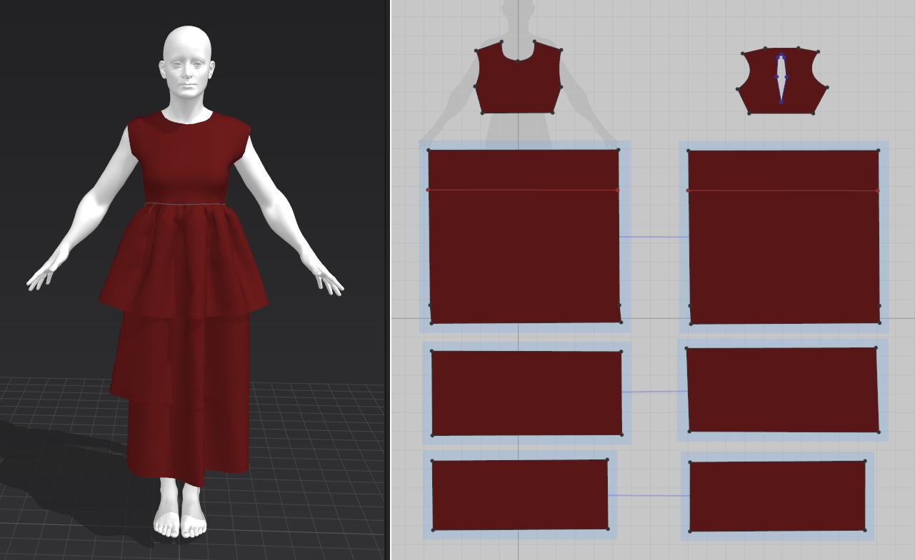
Dress and pattern in a virtual garment design tool.
During the assembly, the original flat 2D panels undergo several transformations. First, each single panel is triangulated. This does not happen independently as edges from different panels that are marked to be stitched together need to have the same segmentation, i.e. number of points and edges. Unfortunately, most tools do not impose equality in length, therefore a long panel edge may be stitched together with a short panel edge, as long as they both consist of the same number of subsections. When stitching those patterns together, the segments of the triangles of the larger panels have to be compressed. That transformation also propagates to adjacent triangles. Below is shown a comparison of the upper skirt layer in stitched and in flat pose. Although the triangles are all sized equally in the pattern, the triangles on the upper edge have been strongly compressed in the stitched version, compared to the lower triangles.
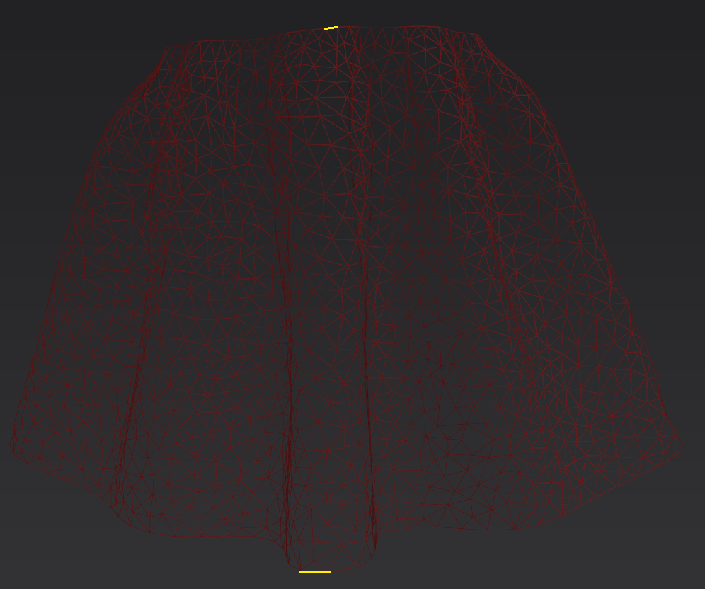
Draped upper skirt layer.
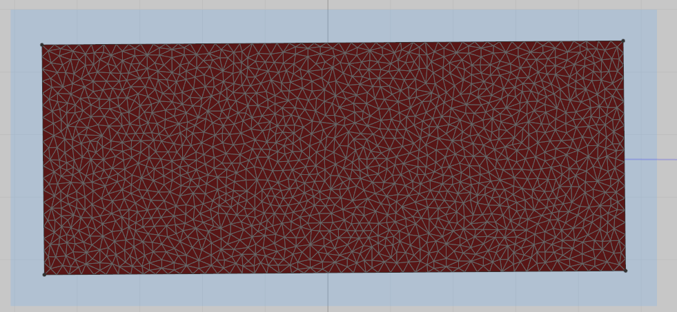
Flat pattern for the upper skirt layer.
In addition to the compression by stitching, almost all triangles undergo an extension in some way as gravitational forces stretch the cloth under its own weight. The sum of these and other transformations (e.g. bending, etc.) leads to a draped geometry which still has the same number of segments and triangles as the original pattern, but their sizes and shapes are deformed.
Directly using this mesh as a simulation mesh means that the Carbon solver will use the deformed geometry as the reference mesh and will try to converge to this state. The big disadvantage of this straight-forward approach is that the dress contains baked-in folds and creases which are very prevalent in the simulation. Secondly, as Carbon also applies gravity, the previously draped dress (design tool drape) is draped again (re-drape with Carbon). These issues can make it hard to achieve a desired look.
All of these problems can be solved using the Tailored cloth model. The Carbon UVs To Points node extracts the original triangulated 2D patterns that the virtual garment design tool has baked into the draped cloth’s uv coordinates. Passing the flat patterns as reference geometry into a Carbon Cloth in Tailored mode ensures that the original metrics are preserved. All folds and deformations stored in the start pose are then literally overwritten and the simulation result reflects a single draping process from flat panels.
More extensive information about all features and advantages of using Tailored Cloth is given in the user guide Tailored Cloth.
UVs To Points
After importing the dress and matching avatar, the scene looks as seen below.

Initial state of the scene.
Next, create a Carbon UVs To Points node from the Carbon/Utils TAB Menu and plug the dress geometry into its input.
If the mesh uvs reflect the actual size of the original panels, nothing else is required. If not, set the correct Uniform Scale. In this case, it is 263.08.
To show the dress and flat panels side by side, we added a Transform and Normal node to the graph.

Applying a Carbon UVs To Points node.
Using Tailored Cloth
Now, create simulation setup.
First, create a Carbon Collider node and attach Avatar, i.e. the collider geometry, to the Carbon Collider.
Then, create a Carbon Cloth node and attach dress, i.e. the dress geometry, to the first input of the Carbon Cloth.
Now, connect both Carbon nodes to a Merge SOP node.
Next, create a Carbon Simulation node and pass the output of the merge into the simulation.
For more information about the common practices and order of steps to set up all Collider, Cloth, and Simulation parameters, please refer to the Avatar Cloth Setup Tutorial.
Now, to use the flat panels as reference for the Cloth, change the Carbon Cloth Model to Tailored, and attach the Carbon UVs To Points to the second input of the Cloth node.
Final Result

Final setup of the scene.