Tailored Cloth
Carbon Cloth in Tailored mode is the most sophisticated cloth model that Carbon has to offer and it supports features such as Anisotropy. It is recommended to always choose this mode for garments which were created from flat panels.
Note
Tailored cloth model only works with triangle geometry!
The name Tailored mode and the way it is used derives from actual garment tailoring. Tailors lay their fabric flat on a table, then place their cutting pattern on the fabric and cut out the individual garment panels. Often the pattern is laid on the fabric in a particular orientation to take advantage of the anisotropic nature of fabric. In Carbon, think of the XY plane as the table and the cloth reference pose as the cut panels. Obviously, this is an abstraction and no actual cutting happens in Carbon, but it is good to keep the comparison in mind, especially when it comes to using anisotropy.
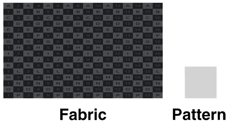
Flattened fabric on a table and a pattern.
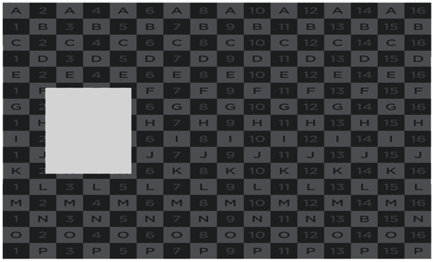
Placing the pattern on the fabric.
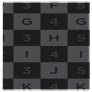
Cut fabric panel.
Anisotropy
Having the 2D panels as the reference pose instead of 3D garments, provides the framework to define the anisotropic properties of the panels. In reality, most fabrics do not behave uniformly. Depending on their weave and fibers, the weft, warp and bias will most likely have different stretch and bending behavior. In order to match this, the Tailored Mode allows the stretch and bend parameters, for weft, warp and bias, to be set independently. Having this capability allows the simulation to get closer to real fabric.
Note
Bias describes any direction which is not aligned with either weft or warp. While only True Bias stands for the exact 45-degree diagonal direction, Bias commonly is used to describe just that, and this is how it is used in Carbon.
Carbon places its virtual cutting table in the XY plane, the weft direction runs along the X-axis, warp direction along the Y-axis and bias runs diagonally.
As most fabrics are stretchier in the bias direction due to the mechanical weave, designers sometimes choose to cut on the bias; where the panel pattern is rotated 45 degrees either clockwise or counter-clockwise. This is usually used for garments that stretch to hug the body.
To demonstrate the effect of anisotropy, three panels of Carbon Cloth are simulated. The only difference between them is how they are laid out in the reference space. This is the same as rotating the panel pattern on real fabric.
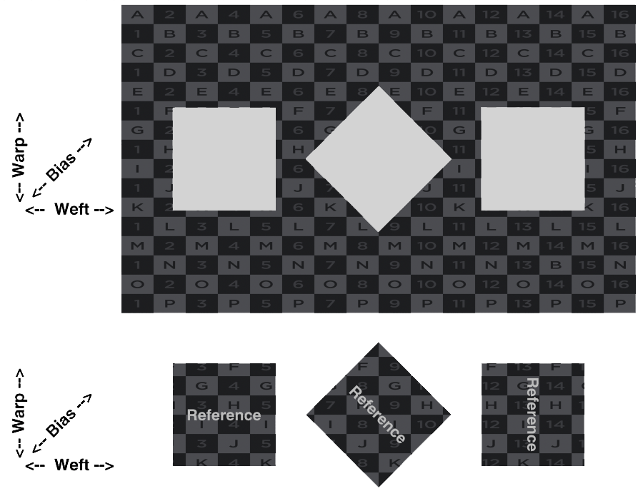
Panel pattern in different layout directions.
This example shows how different the simulated results can be depending on how the anisotropic parameters are set up. In this case, the Stretch Stiffness is set to be very strong in weft direction (Base Value of 5 and Weft Factor of 100) and normal in warp and bias directions (Base Value of 5 and Bias/Warp Factor of 1).

Simple anisotropic cloths with high Segment Stiffness in weft direction.
Note
Standardized tests like KES-F, FAST or FAMOUS provide information about the ratios between weft, warp and bias extensibility and bending properties for fabrics. Although Carbon does not have the interface to incorporate the test results directly, they can be used to guide the Carbon Cloth parameter setup.
Preservation Of Metrics
Garment design tools allow the creation and stitching of panels into garments. Those panels are created in 2D space and draped in 3D onto an avatar. The image below shows such a stitched and draped garment, as well as the panels from which it was made.
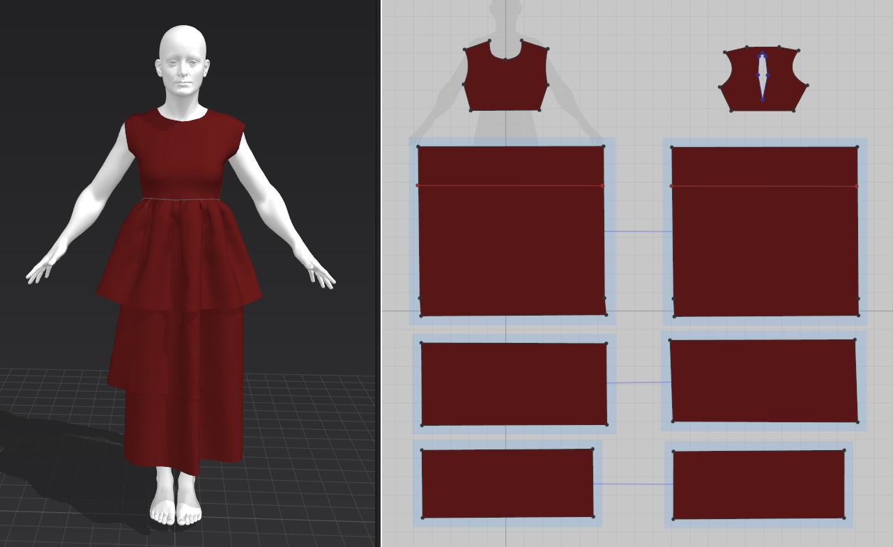
Dress and panels in a garment design tool.
During the assembly, edges from different panels that are marked to be stitched together are set up with the same number of points and segments. As most tools do not impose real world constraints and equality in length for such edges, a long panel edge may be stitched together with a short panel edge.
This leads to a compression of the larger edge during the assembly process, which also propagates to adjacent triangles.
Below is shown a comparison of the upper skirt layer in stitched and flat pose. Although the triangles are all sized equally in the panels, the triangles on the upper edge have been strongly compressed in the stitched version, compared to the lower triangles.
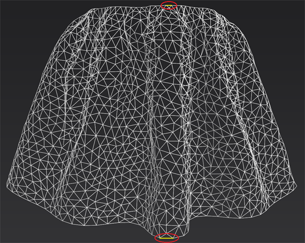
Draped upper skirt layer.
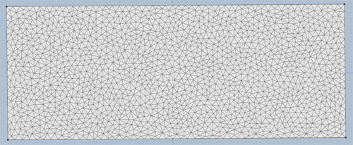
Flat panel for the upper skirt layer.
As Carbon aims to provide realistic simulations it can help designers detect flaws in digital garments at a very early stage. For a badly tailored garment like the skirt shown above, the Carbon simulation will give immediate feedback as the Tailored cloth model applies the original edge lengths, which then leads to an expansion of the upper edge of the skirt during the first simulated frame.
In addition to the compression by stitching, almost all triangles undergo an extension as gravitational forces stretch the cloth under its own weight.
If we were to directly use this draped geometry mesh as a Carbon simulation reference mesh, then the Carbon solver would try to converge to this already deformed state, essentially redraping a draped mesh, which is unlikely to result in the best look: The skirt would be too long and possible too wide.
This redraping can be avoided by using the Tailored cloth model, which ensures that the original metrics of the 2D flat panels are used as the reference mesh.
Maintaining Panel Size
Although the original metrics of the 2D flat panels are used as the reference mesh, it should be remembered that any open edge in the final garment will also have the Fatness / Thickness added to its length for collision purposes.
Often, in practice, this is can be ignored. However, if you have a situation where exact collision matters, for example a lapel and a collar that meet exactly with open edges or two open edges you want to stitch together at exactly the correct size, then you need to reduce the panel size at the open edge by the Outer Fatness size, which is also half the thickness of the cloth.
Note
When you fuse panels in Tailor Mode, it is ONLY the edges that are left open in the final garment that have fatness. All the panel edges that are fused are not impacted by this. So, it is only the open edges in the final garment that should be trimmed. Edges that you stitch together with Carbon constraints (binding, welding, stitching etc.) are also open edges in this context.
Preservation Of Angles
Using a flat Reference guarantees that all reference angles are flat, therefore all creases in the Start Pose are non-permanent. While Flat Angles in the Face-Segment-Crease cloth model is optional, the Tailored cloth model enforces flat angles by default and the simulation result will now reflect a single draping process from flat panels. In the Tailored cloth model there are often some angles that should be preserved from the original 3D draped garment from the design tool, such as for pockets or seams in general. The Tailored cloth UI provides a Flat Angle control to allow this.
Creation of Realistic Garments Simulations
It is important to realize that a virtual garment needs similar design features to real garments, if it is to simulate like a real garment. We would encourage anyone trying to create realistic garment simulations to learn from existing patterns to model their garments, or get someone involved in the design process that understands garment design. The quality of the garment design has a huge impact on the quality of the resulting simulation.