N-Lattice
The Carbon N-Lattice is one of the most versatile nodes that Carbon has to offer. It can be used for hair, fur, foliage, plants and plumage.
A Carbon N-Lattice takes an input mesh made of multiple lattices and turns them into a multitude of hybrid dynamic object where each individual lattice consists of a Carbon Soft that is partially welded to a Carbon Rigid frame and controlled through some Carbon Joints to manage its attachment as well as swing and twist behavior.
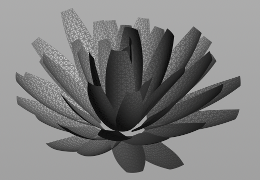
An N-Lattice input mesh composed of multiple lattices and ready for simulation.
Lattice Topology
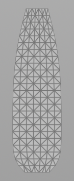
A single lattice is a simple two-dimensional grid and can come in a variety of sizes and tessellations. Some examples for lattices are shown below:
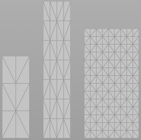
Different types of lattices.
We call the left lattice a 3x4 lattice, as it has 3 base points and is 4 points tall. Therefore, the other examples are called 5x8 (middle lattice) and 10x15 (right lattice).
Note
We do not restrict the lattice in terms of maximum resolution, but require a minimum resolution of 2x2.
As Carbon internally works with triangles, it is recommended to triangulate all lattices before using them in Carbon N-Lattice. The reason for this is that the tessellation matters because it describes the degrees of freedom where the physics will be able to bend.
Furthermore, it is especially important to avoid triangles with 2 edges on the outline of the lattice.
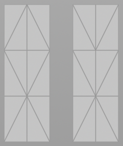
Bad triangulation (left) vs good triangulation (right).
The left triangulation is bad as the upper outer triangles do not have enough angular restrictions and are easily susceptible to flapping during the simulation.
Note
Using a Houdini Edge Flip node allows to easily fix such cases of bad triangulations.
It is therefore strongly recommended to work with triangulated lattices so that any potential problems can be spotted easily.
Besides the pure topological information, the guide serves a second purpose.
It describes which of the points should be welded to the rigid shaft.
This is done via a point attribute called shaft.
All points that are part of the shaft are soft-welded to a rigid object.
This rigid shaft allows us to create a mechanical constraint, which we can then use to control the orientation of the entire lattice and allow angular swing animation of any lattice of the Carbon N-Lattice. Look at the screenshot below for good examples of how to choose the points for the shaft.
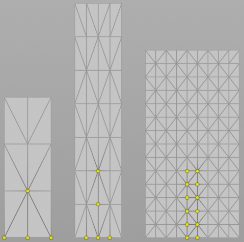
Choosing points for the shaft.
As you can see, the left lattice has got the whole bottom row marked as shaft. This is because it is important that there are enough vertices which are constrained to the rigid frame, as otherwise the soft part of the lattice would be free to rotate around the shaft. Similarly, the middle lattice also has the center-adjacent points marked as shaft, but not the complete bottom row. This ensures that there is still enough degrees of freedom for the lattice to deform in constraining situations.
Furthermore, just as with Carbon Plumage soft feathers, all attributes contributing to the soft/cloth behavior can be painted on the guide to influence the simulation. This information is then shared between all the lattices in the Carbon N-Lattice.
Individual Poses
A single mesh is used to provide a pose for the entire set of lattices, while each individual lattice can be deformed in the likes of:
- Stretch/Squash
- Bending
- Twisting
- Moving individual points around for a unique shape
- Uniform/non-uniform scale
The user has unrestricted freedom to deform the lattices, as long as they are made from the same grid topology as the guide. An example of a deformed lattice with better collision shell would be:
Tapered top and bottom provide a better collision geometry.
Bringing the outer points on the bottom line closer to the center can avoid over-constraining the vertices that are welded to the rigid shaft with near neighbor collisions. This will heavily reduce the risks of conflicting constraints and jittering.
Note
When deforming individual lattices, keep in mind that this can lead to tiny triangles or splinter triangles, which can invert or corrupt the simulation. It is best to avoid such extreme cases.
The individual lattices can then be further customized using painted primitive attributes for Swing Stiffness, Swing Viscosity, Twist Stiffness, and Twist Viscosity, to create individual characteristics for each lattice.
Warning
Painted primitive attributes must be set uniformly for all primitives contained inside a specific lattice.
Growth And Swing
Similar to Carbon Plumage, the beginning of each simulation can have a growing and swinging process to produce a physically correct laminated starting pose, as described in the image below.
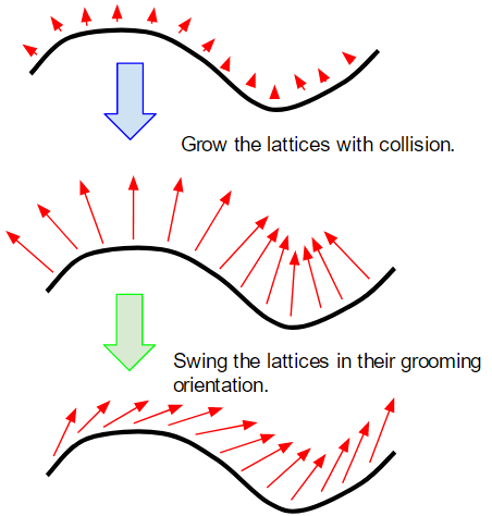
Growing lattices and swinging them into their final state.
This process is part of the Carbon N-Lattice node and automatized for ease of use. It gives the user the option to grow the lattices from a scaled-down representation to their desired scale of the reference pose. After that, the user can take advantage of our ability to animate the mechanical representation and swing the lattices into their desired groom orientation.
With the collision detection and resolution always active, the lattices repulse one another instead of intersecting and corrupting.
Growth
The easiest way to grow lattices is to rely on the integrated and automatized feature of Growth Lead-In. Simply specify the length of this lead-in in frames and the rest is done automatically.
Advanced users may want to control the scaling process manually by animating the N-Lattice Geometry, in which case simply set the Growth Lead-In to zero. Make sure to tick Animated Geometry as otherwise no update will happen.
Swing
Since each lattice is attached to a rigid frame, we can set or animate the swing angle of each lattice. This feature can be used to swing lattices into their final orientation during or after the growing/scaling process.
The easiest way to swing lattices is to rely on the integrated and automatized angle extraction and interpolation over a timespan of Swing Lead-In frames.
Note
If Swing Lead-In is set to 0, all lattices are spawned in their final swung state. This is generally not recommended as it is very likely to result in intersecting lattice geometry, which leads to corruptions during the simulation. But, there are applications where it is best to spawn all lattices in their final angular state and simply grow them in place. The decision of whether to spawn in the final state or to spawn along the normal and then swinging into place really depends on the application. If all lattices are already layered and laid out perfectly, it could be counter-productive to ignore the setup and completely redo the lamination process.
Uniform Angles
Swing angles can be set uniformly for all lattices using the Override Angles parameter. The Override Angles is applied based on the individual lattices’ orientation in the N-Lattice Geometry. The Swing Lead-In parameter dictates the number frames it will take to swing Override Angles degrees.
Non-Uniform Angles
Besides the N-Lattice Geometry, an additional Groom Pose can be specified, which is used to provide all individual angles. In contrast to using the Override Angles, this allows to swing lattices non-uniformly, meaning some might not swing at all, while others might swing 90 degrees or more. If a Groom Pose is provided, the N-Lattice Geometry must describe all lattices in normal configuration. The Swing Lead-In parameter dictates the number frames it will take to swing each individual lattice from N-Lattice Geometry to Groom Pose.
To use this feature and possibly rescale/limit all angles, switch from Override Angles to Groom Angles Angle Limit.
Note
Groom Angles Angle Limit is only enabled when a Groom Pose is provided.
Advanced Usages
When relying on the Swing Lead-In feature, keep in mind that the swinging process is performed after scaling the lattices, that means it is delayed by the number of Growth Lead-In frames. If scaling and swinging is meant to happen at the same time, you need to set Swing Lead-In to 0 first. Then, there are 2 options:
- Animate the Override Angles for uniform angles or Groom Angles Angle Limit for non-uniform angles. In either case, make sure to tick Animated Angles as otherwise no update will happen.
- Directly animate the N-Lattice Geometry. Make sure to tick Animated Geometry as otherwise no update will happen.
N-Lattice Vs Plumage
As mentioned, the Carbon N-Lattice node can also be used for plumage, instead of working with a Carbon Plumage. This section explains the differences between the two approaches and how to decide which one is most suitable for a specific plumage application.
First of all, Carbon Plumage works with soft and hard feathers, while Carbon N-Lattice only supports lattice simulations that can be used for soft feathers.
For soft and hard Carbon Plumage, we only require the user to specify 1 to 3 base feathers and the system then interpolates between these to generate the individual feathers in a procedural manner. Our target for the soft and hard plumage was to provide a fast and easy way to create and simulate feathers on creatures. This feature is perfect for applications where smaller creatures or a large amount of creatures have to be created fast, removing the need for artists to place and deform each feather individually, therefore cutting production time and cost. For examples of these type of plumages, please refer to Plumage Introduction and Multiple Plumages.
On the other hand, creating plumages with Carbon N-Lattice is most suited for hero-creatures, which usually come with a whole set of feathers. These feathers are carefully placed and deformed individually, often manually, in very specific and unique ways. With the feathers having been created by skilled artists, the plumage is ready for simulation without the need for Carbon to procedurally spawn and deform them. Carbon N-Lattice directly works with complete sets of lattice feathers within a single geometry to cater to such applications.