Avatar Morph
This tutorial outlines the recommended sequence for setting up the Carbon Simulation parameters for an Avatar used as a Carbon Morph.
A general understanding of Houdini and Carbon and some advanced techniques are required to understand this tutorial with ease, it therefore is recommended to read Carbon Morph, Avatar Cloth, and Painted Attribute Maps first.

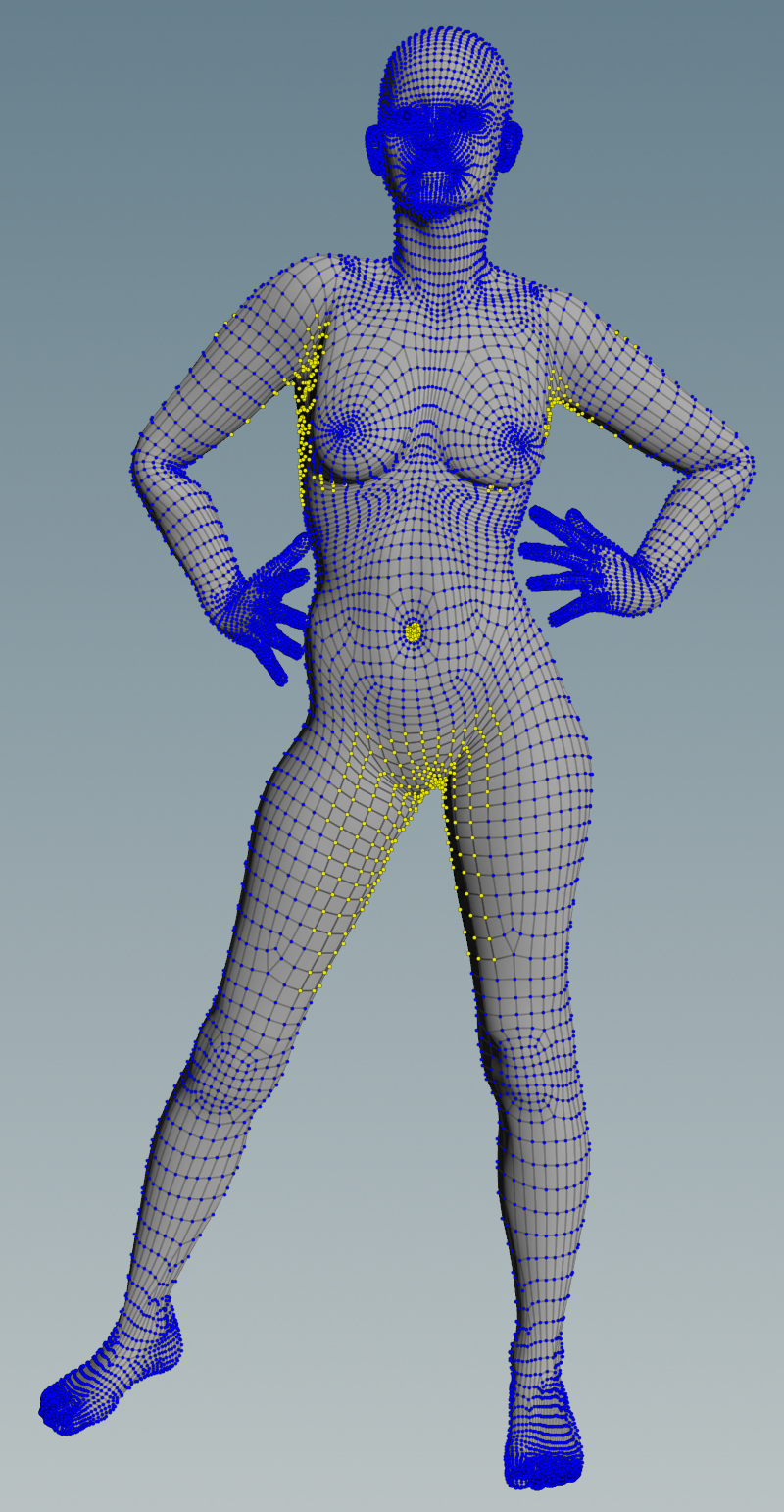
Initial state of the tutorial scene.
The screenshot above shows the initial state of the tutorial scene which contains an animated character and two pieces of clothing.
Note
Most modeled, rigged and skinned characters are provided as regular quad meshes. Such meshes are well suited for rendering but too regular for physics simulations. Depending on the quad mesh tessellation, sometimes it is best to convert meshes to Delauney triangulated meshes for all simulations. After the simulation stage, capture the triangle mesh with the original quad mesh for rendering.
Initial Simulation Setup
Following all steps outlined in Avatar Cloth, we reach a simulation setup as seen below:

Initial state of the simulation of tutorial scene.
Unfortunately, once we run the simulation, we quickly end up with heavy corruption of the Top Cloth in the armpit areas.
Pinching and Dragging
There are various factors which can lead to pinching and dragging of a Carbon Cloth by a Carbon Collider. The most common reasons are unsuited animations which move body parts through another and non-optimally tailored pieces of clothing. But even well-designed setups might result in geometry corruption and inter-penetration.
The top in this test scene is cut to leave small sleeves and material up to under the armpits. While the animation is almost free of self-penetration, there is not enough space between the arm and the torso to fit the top. The screenshots below show how, due to the lag of space, the cloth is pinched between the arms and the torso, which leads to dragging and geometry corruption.

Situations where cloth is corrupted by the collider.
Collision Analysis
As explained in Avatar Cloth, the Carbon Collider is capable of running a complete self-analysis to mark areas critical to cloth corruption.
There are 5 basic steps to create and retrieve the results of the analysis:
Deactivate all nodes but the Carbon Collider.
Introduce a Filtering Gap (set this to at least the thickness of the Carbon Cloth being pinched).
Activate Self Analysis.

Setting up the collider for self-analysis, steps 1-3.
What you see visualized above is the Collision Analysis Physics Draw of the Carbon Collider. Areas marked in red are primitives that intersected during the last frame.
Note
Especially when dealing with fast animations, intersections will often happen during subframes. Carbon captures these as well.
Areas marked in blue are all primitives that intersected since the beginning of the analysis.
Attach a Carbon Simulation Geometry node to extract the simulated Carbon Collider geometry.
You can use a Color node to visualize the analysis point group.

Extracting and visualizing the self-analysis results, steps 4-5.
Now, simulate to the last frame and lock Carbon_Simulation_Geometry1. We will use this geometry to create a Cloth Point Group and Goal Skin Paint Map for the Carbon Morph.
Note
The Collision Analysis Physics Draw is not cached by Carbon, so when replaying from Carbon cache, you will always see the Collision Analysis Physics Draw of the last simulated frame.
Cloth Point Group
While it is possible to set the Cloth Point Group to * and rely on the Goal Skin Upper Threshold parameter to control which points are kinematic, it is usually easier and more efficient to specifically set the Cloth Point Group parameter.
First, let’s remind ourselves that any point not included in the Cloth Point Group will be kinematic throughout the whole simulation, so it is often better to be a bit more generous in selecting Cloth areas.
Now, there are two main ways to use the analysis point group: Use it as guidance and create a new group from scratch, or modify the group.
In this case, we chose to modify the analysis group.
There are two things we will do to modify the group: Clean and Expand.
Starting from the group:
Original analysis group.
Let’s first remove the points under the breasts and at the belly button, because we know that they do not cause any issues. Also, we can remove the points on the legs as they did not cause any issues with the skirt.

Cleaned-up analysis group.
As a last step, we like to use a Group Expand. Expanding the group by 1 or 2 steps will not only help fill gaps, but it makes the simulation more stable in most cases as it adds more cloth to critical areas.
Warning
Areas where fully kinematic points transition to dynamic points can be problematic when dealing with geometries that undergo extreme deformations. Hinging and pinching can lead to overconstraints and to the simulation blowing up. In such cases, it is best to either increase or decrease the cloth area, or even go so far as to turn the complete object dynamic, and heavily constrain all former kinematic areas using high Goal Skin Strength values.

Expanded analysis group.
Goal Skin Paint Map
Goal Skin Strength is a paintable attribute, and we recommend reading through the Painted Attribute Maps User Guide first.
In conjunction with the Cloth Point Group, Goal Skin Strength (painted point attribute name goalSkinStrength) decides which areas of the avatar will be fully dynamic (unconstrained), constrained dynamic (partially constrained) or kinematic (fully constrained, i.e. not simulated).
We can use a Point Wrangle and Attribute Blur node to create the paint map directly from the Cloth Point Group.
Note
It is recommended to perform at least a single smoothing operation, such as applying an Attribute Blur (or smooth after painting the attribute by hand using an Attribute Paint node) when dealing with painted attribute maps where large areas without obvious sharp geometric borders are painted. The resulting gradient will usually result in a smoother simulation.

Goal Skin Strength Paint Map.
Warning
Beware of the transitions between kinematic and dynamic areas. If a collision was later to happen in these zones, the simulation would become overconstrained and most likely blow up. Therefore it is important not to create such transitions where the analysis has detected interpenetrations.
Carbon Morph Setup
We can now replace the Carbon Collider by a Carbon Morph.
The Carbon Morph setup should be done in two steps. First, set the general cloth/collider attributes, then adapt the Goal Skin Strength parameters.
Note
Do not forget to edit the Numerion Carbon Binding node to use the morph instead of the collider.

Morph Simulation Setup.
Warning
If you are working with a single-sided Morph, it is often necessary to adjust the Inner Fatness values. As the simulation goes, dynamic and kinematic areas can interact from inside the surface. This could create an overconstrained situation that will lead to the simulation blowing up. There are extreme cases where any Inner Fatness value will result in the simulation blowing up. Usually, this is an indicator of splinter triangles, triangle inversions, and other unsuitable geometry and/or animation. You should fix these problems whenever possible at the modeling/animation stage. Otherwise, turn the geometry into a double-sided geometry and rely on a larger Thickness.
There are four main parameters which need to be set regarding the goal skin:
- Base; default value: 10.
- Range; default value: 0.
- Lower Threshold; default value: 0.
- Upper Threshold; default value: 1.
Goal posing is an artistic and very powerful feature and it might take beginners several attempts to get a good parameter setup. The following steps give general guidelines on how to proceed most efficiently.
First, keep all default values and tick the Physics Draw Draw Goal box. Then set the Carbon Morph’s Cloth Point Group to * to make all points dynamic and constrained. In this state, each point of the surface will be drawn in a yellow-green color. This means that all points are dynamic constrained right now. Red would indicate kinematic points.

Goal skin default parameters.
Now, set the Base value. A good value is large enough to keep the avatar body from falling under gravity, but not much larger. Too small of a value will later allow the body to easily deform, while too large of a value preserves the shape too much and still corrupts the cloth. In this example, the default value of 10 is a good value.
Now that the Base value is set, set the Carbon Morph’s Cloth Point Group to the cleaned and expanded point group.
Next is the Painted Attribute Range, which scales the painted point attribute values and their product is added to the Base value. The final goal skin strength value therefore is \(value = base + range * attribute\). For more information, please refer to Painted Attribute Maps. Moreover, the sign of Painted Attribute Range decides whether the painted attribute map is applied in an additive or a subtractive manner (whether we paint the areas which should be dynamic or the areas which should be kinematic).
- Positive Painted Attribute Range values treat the map as additive: painted areas are kinematic areas.
- Negative Painted Attribute Range values treat the map as subtractive: painted areas are dynamic (constrained) areas.
At this stage, ignore the absolute value and set the range only based on the sign, e.g. -1, as we are dealing with a subtractive map.
The thresholds control which areas are kinematic, dynamic constrained or fully dynamic.
Note
The adjustment of the Upper Threshold and Lower Threshold parameters have the effect specified only once that the Goal Skin Painted Attribute Range parameter has been set to a non-zero value. Therefore it is important to follow these instructions in the specified order.
There are certain rules in regards to these thresholds:
- If Lower Threshold is 1 and Upper Threshold is 1, all points are fully dynamic, regardless of the Painted Attribute Range.
- If Lower Threshold is 0 and Upper Threshold is 0, all points are kinematic, regardless of the Painted Attribute Range.
- If Lower Threshold is 0 and Upper Threshold is not 0, there are no fully dynamic points, regardless of the Painted Attribute Range.
Additionally for a positive Painted Attribute Range, depending on each point painted attribute value:
- If the painted value is smaller than Lower Threshold then the point is set to be fully dynamic.
- If the painted value is larger than Upper Threshold then the point is set to be kinematic.
And for a negative Painted Attribute Range:
- If (1 - painted value) is smaller than Lower Threshold then the point is set to be fully dynamic.
- If (1 - painted value) is larger than Upper Threshold then the point is set to be kinematic.
These rules seems complicated, but with the help of the Goal Skin Guide Geometry changing the dynamic/kinematic zones is a simple matter of moving the Lower Threshold and Upper Threshold sliders until the colors show in the correct regions.
For deformable characters, as in this scenario, it is unusual to allow fully dynamic areas as the character shape will not be preserved at all. Therefore, the first step is to set the Lower Threshold to 0 (which is the default value). So, all points are dynamic constrained.
Since we are controlling which points are kinematic via the Cloth Point Group, we can also leave the Upper Threshold at its default value, i.e. 1.
There are 2 other goal skin related parameters, but they do not have to be altered for this example:
- Goal Skin Velocity Limit: This describes the maximum velocity between a simulated and an animated node. This parameter is used to control overshooting and jiggling induced by a strong goal skin strength. Reducing the Goal Skin Velocity Limit slows down the simulation relatively to the animation and allows for smoother motions.
- Goal Skin Viscosity: This copes with fast motions in animations. If the avatar was to accelerate fast, large values for Goal Skin Viscosity incorporate that motion and help the simulated skin to keep up with the animation.
At this point, run the simulation to see whether the deformations on the character skin is too strong, not strong enough, too large of an area, or too small of an area. Then either adjust the Painted Attribute Range if the scale of deformation is wrong, or the paintmap if the area is wrong.
After a few simulation test runs, a Painted Attribute Range of -4 proves to be a value that produces appropriate skin deformations while no longer causing cloth corruptions.
In summary:
- Base: 10.
- Range: -4.
- Lower Threshold: 0.
- Upper Threshold: 1.
Finally, for visualization purposes, extract all relevant Simulation Geometry, and merge it.

Final setup.
Another Example