N-Lattice Fern Setup
N-Lattice is a complex node and we recommend to first study the Avatar Cloth tutorial for in-depth information on how to set up a Carbon Simulation with a Carbon Collider and Carbon Cloth.
Then, please read the N-Lattice User Guide before continuing on this tutorial.
As most foliage systems natively work with lattice geometry, Carbon N-Lattice is making it even easier to integrate Carbon into existing workflows for all types of plants and foliage applications.
Having the option to use lattice guides with different resolutions makes this new feature so versatile that it can be used to simulate a large variety of plants, ranging from thousands of low-resolution leaves on a tree to a few dozen high-resolution fern leaves.
For the remainder of this tutorial, we will demonstrate how to use the Carbon N-Lattice to set up and simulate a fern that is exposed to wind.
Base Lattice
The base lattice for a fern leaf should be rather detailed. For this tutorial, a 8 x 25 point resolution is sufficient.
Use an Edge Flip node allows to quickly fix any triangulation issues where certain triangles have two outside edges.

Detailed fern lattice.
The next step is to set up the lattice shaft, which marks which points are welded to the rigid shaft.
Note
Remember to never only select a single row of vertical points, as this would result in a constraint where twisting freely can not be prevented.
In this case, the lattice geometry is quite tall, so we chose to extend the shaft quite high to have enough rigid support. Furthermore, to ensure a stable attachment at the root, let’s select a wider range of points towards the bottom part of the lattice.
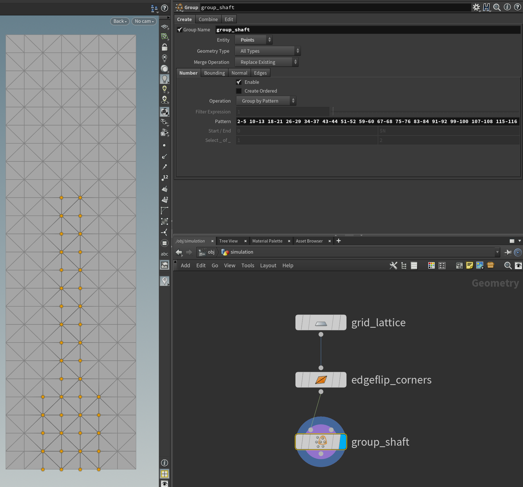
Creating the shaft point group.
Since we want the root of the lattices to be attached quite firmly, and the attachment strength slowly tapering off towards the tip, it is quite important to paint the welding stiffness of the lattice. If we did not use a painted attribute here, we would most likely end up in a situation where either the root would be attached too loosely, or the higher up attachment points would be attached too rigidly, preventing smooth bending behavior of the lattices.
So let’s add a weldingStiffness point attribute and paint it as a smooth gradient:
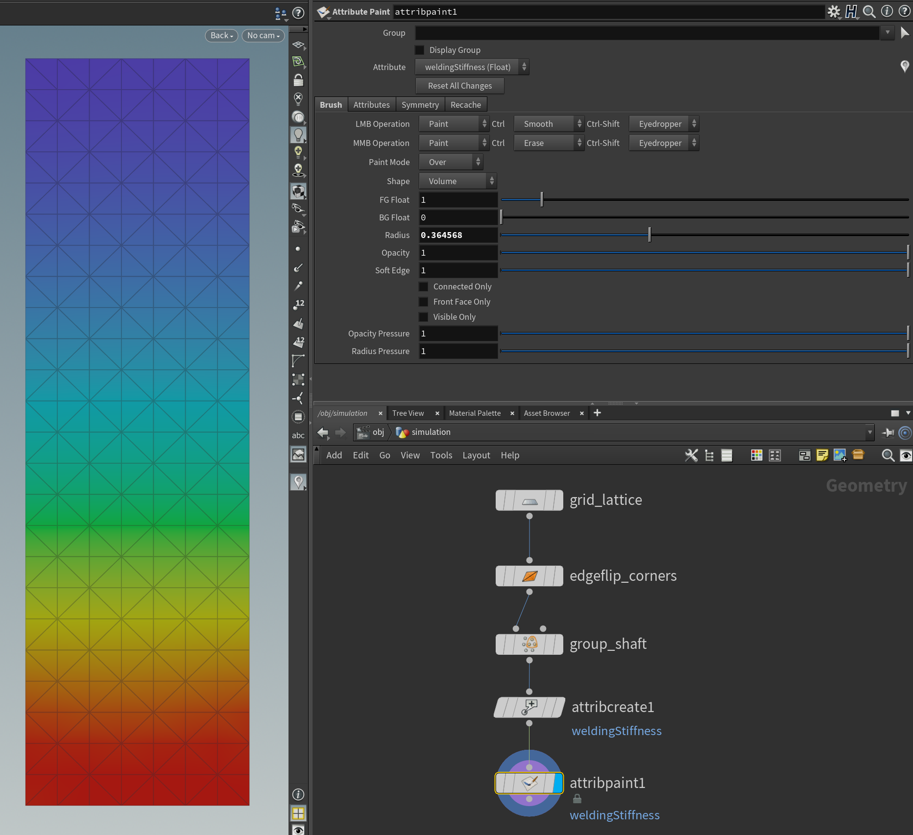
Painted Welding Stiffness.
N-Lattice Geometry
This process, where the base lattice is deformed and placed on the ground, or any other relevant underlying objects, varies strongly from application to application. For fur it might be a dog, for hair a human head, for feathers a bird, for leaves a tree, etc.
In case of a fern, each individual leaf could be sculpted to specific targets if the plant was the center of a scene, while on the other hand, they might all remain the same and any visual differences might only be added at the render stage.
For this tutorial, variations of the lattice are created procedurally and they are automatically placed in a circular fashion.
As a first step, the rectangular lattice is deformed to receive the general shape of a fern leaf.
The deformation is done by using the Taper operation in two Twist nodes, which taper the top and bottom of the rectangular lattice to achieve a rounder look.
Not only is this a visual improvement, but also helps to avoid over-constraining the vertices that are welded to the rigid shaft with near neighbor collisions. This will heavily reduce the risks of conflicting constraints and jittering at the base.
Next, we apply two more Twist nodes, to bend the lattice geometry along 2 axes.
We then use a For Loop and a Copy Stamp to procedurally build a whole fern by spawning lattices in a circular manner, varying sizes, and colors.
See below for step by step results:

Deforming the base lattice and then spawning one lattice per point in a hemisphere geometry.
Simulation Setup
The simulation consists of a floor and a fern, which grows at first, and once it has stopped growing, some wind starts blowing:

Simulation Setup.
The rest of this tutorial focuses on how to set up the Carbon N-Lattice node. For more information on how to set up a basic Carbon Simulation with a Carbon Collider, and Carbon Cloth, please refer to Avatar Cloth.
N-Lattice Parameters
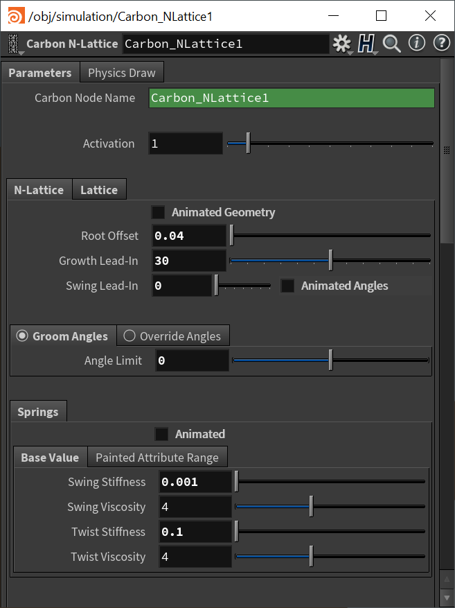
N-Lattice parameters.
For the first step to setting up the Carbon N-Lattice node, stay in the N-Lattice tab.
As we are not animating the lattice geometry, make sure to untick Animated Geometry as it decreases solver speed when left ticked.
Also, as we do not need to swing the lattices in place, set Swing Lead-In to 0 and untick the Animated Angles box.
Next, set the Root Offset to at least the Collider Outer Fatness. This offsets each lattice along its shaft vector to ensure that it will not intersect with the collider at startup.
Note
If your root offset is too small, you will see jiggling / fighting at the roots, where the welding constraint fights the Collider collision.
Growth Lead-In is changed to 30 to make the automated growing process more stable.
Note
If you notice objects intersecting / corrupting during the growing process, try to increase Simulation Subdivisions and / or increase Growth Lead-In to decrease the incremental growth per frame.
Make sure to select Groom Angles and set it to 0 to avoid any change in angles.
Springs
Swing Stiffness and Swing Viscosity control the swing/flapping behavior of the lattices. High values for Swing Stiffness guarantee that the lattice stay close to their target angles while low values allow for a feeling of lightness.
Twist Stiffness and Twist Viscosity control the twist behavior of the lattices, which is the rotation around the shaft. Similar to the swing parameters, high values prevent additional lattice movement.
So, we want to set the Swing Stiffness rather low to allow the leaves to swing in the wind, but set Twist Stiffness higher to prevent the leaves from rotating too much.
There is no generally most suitable parameter setup for the spring parameters. Animated N-Lattices with strong deformations require lower stiffness values to avoid corruption of the lattices while fast N-Lattice animation relies on high stiffness values to ensure that the lattices follow the animation. It is recommended to start with low values for Swing Stiffness and Twist Stiffness and low values (1 or 2) for Swing Viscosity and Twist Viscosity, then to adjust these values as required. Starting with Swing Stiffness: To tune the values, set both stiffness values close to 0, turn off all N-Lattice and Collider animations, and run the simulation to see how the lattices behave during the growing and (optional) swinging process. If the value is too low, it will be very obvious, as you can see in the screenshot below.
Too low Swing Stiffness.
Increase the stiffness by a magnitude of 10 and try again; iterate until a value stiff enough is found. Then repeat this process for Twist Stiffness. Generally, keep in mind that you might have to adjust these values once you turn on animation again, if there is one. In this scene, adding Carbon Flow needs to be taken into consideration.
As we are not animating Springs parameters, make sure to keep Animated unticked to slightly improve performance.
Lattice
Now, switch to the Lattice tab and set the Shaft Point Group.
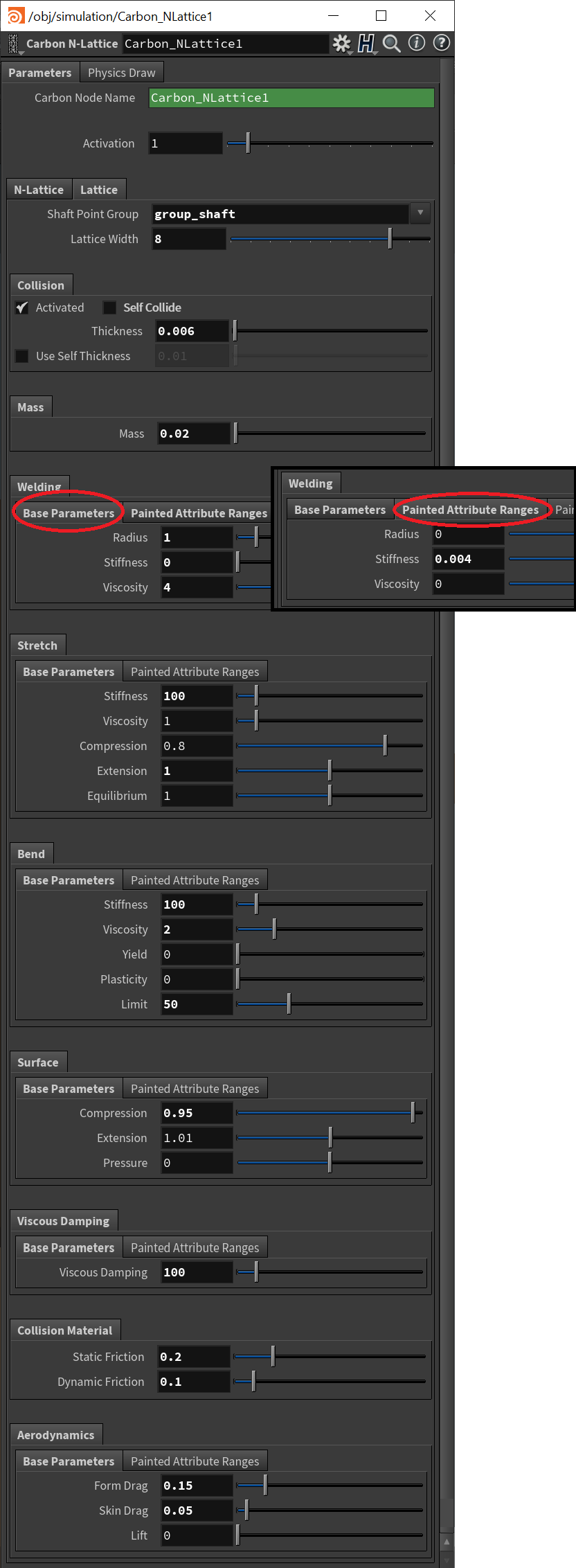
Final Lattice parameters.
Next, set the Lattice Width, which refers to the number of points on the base of the grid. In this case, the width is 8.
Warning
It is important to set the correct value for this parameter so that the lattices’ position and center of mass can be correctly calculated. Using an acceptable but wrong value (such as the grid height instead of width) will not give an error but still yield a visual result that will simulate incorrectly.
After setting Thickness and Mass, we need to increase the Welding Radius and tune the Welding Stiffness to apply our paintmap.
Note
Please refer to Plumage Introduction for a detailed description of the recommended steps to take when setting up welding radius and stiffness.
After that, set all soft properties. Detailed information about how each parameter influences the simulation can be found in Avatar Cloth.
Since the lattices are very long, we need to drastically increase Bend Stiffness to reduce bending. Furthermore, reducing the Bend Limit helps prevent sharp / small folds.
Additionally, set Viscous Damping to 100 to prevent jittering, other fast motions, and achieve a very cohesive behavior without local flapping.
Finally, set low values for the friction terms to avoid the leaves from sticking to each other and make sure to set all Aerodynamics parameters properly to achieve a pleasing result. For more information about friction or aerodynamics, please refer to Friction and Aerodynamics.
Note
The hardest aspect of setting up long lattices often is to find a balance of Springs parameters and Welding parameters, to be more precise: Swing Stiffness vs Welding Stiffness. Sometimes, it can help to change the order of setting these two parameters up. For example, set the Shaft point group to include all points and set the Welding Stiffness to a very high value. This means that all points of each lattice are now welded to the rigid shaft, and with the Welding Stiffness high enough to prevent points from moving away from the shaft, we now can tune the Swing Stiffness much better. And vice-versa, it can be helpful to first set a very high Swing Stiffness, preventing the feather’s Rigid to swing. So, when there is a collision situation that is overconstrained, the Welding Stiffness is what needs to be low enough to allow for the soft part of the lattice to deform / move.
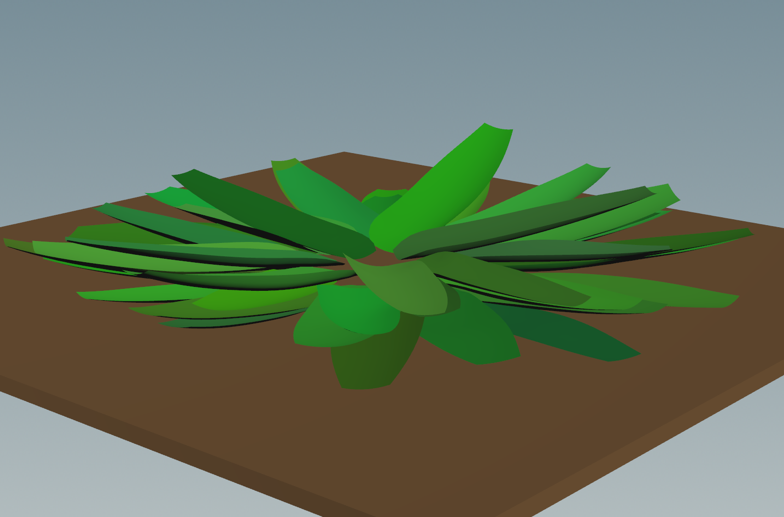
The final simulation can be seen below.

Final simulation.